note |
Frequency Extension System is available for C4409 and C4420 models. |
Frequency extension modules (Modules) are designed to expand the frequency range of the Cobalt Series Analyzers. Modules are operated in conjunction with the Analyzer only. They cannot be used for measurements without a connection to the analyzer. The modules include the following basic elements: test/RF and LO signal frequency multipliers, a wide-band power amplifier, directional couplers, frequency converters. They also include power supply circuits and a control board. The measurement system includes:
•The Cobalt Series Analyzer (C4409 and C4420) with the configurable front panel for connection to Modules.
•Frequency Extension Modules (See table below).
•Cables for connecting Module to Analyzer.
The measurement system is controlled by the Analyzer software. The number of Modules used in the measuring system is determined by the configuration of the Analyzer in use.
Supported frequency extension modules are represented in the table below.
Module |
Frequency range |
Connector type |
|---|---|---|
FET1854 |
18 GHz to 54 GHz |
NMD 1,85mm, male |
FEV-15 |
50 GHz to 75 GHz (V band) |
WR-15 |
FEV-12 |
60 GHz to 90 GHz (E band) |
WR-12 |
FEV-10 |
75 GHz to 110 GHz (W band) |
WR-10 |
Custom |
— |
— |
Principle of Operation
The diagram of the measurement system is shown in the figure below.
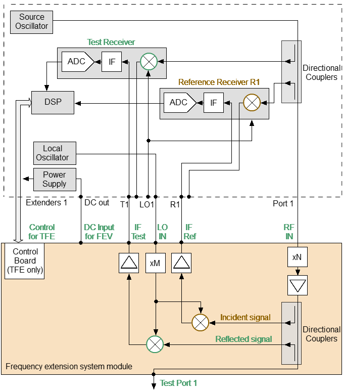
Diagram of Module connection to Analyzer
The Analyzer generates RF and LO signals in specified frequency and power ranges. The signals are transmitted to the Module through RF and LO cables.
The frequency of the RF signal transmitted from the Analyzer is multiplied, filtered, and scaled in the Module to level depending on user settings.
Then, the generated RF signal is transmitted to the test port via directional couplers. The directional couplers extract the incident wave, the wave transmitted through the DUT, and the reflected wave. These signals are supplied to frequency converters for the test and reference channels. The LO signal from the Analyzer is used for conversion. The converted IF signals are amplified and passed to the Module output and then the Analyzer input via IF cables.
In turn, the Analyzer performs digital signal processing of the IF signal. An external PC uses the Analyzer software to calculate and display measurement results for complex transmission and reflection coefficients.
The C4409 and C4420 Cobalt series Analyzers have additional ports with jumper cables on the configurable front panel for connecting frequency extension systems. Connectors for controlling and powering Modules are located on the rear panel of the analyzers. Location of the connectors for the Cobalt C4420 model is shown in the figure above.
Configurable front panel and control/DC cable connectors on rear panel
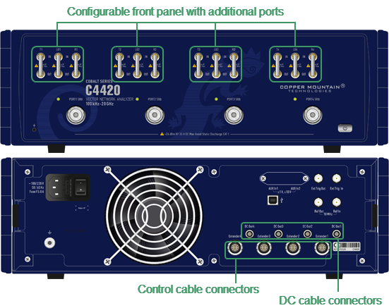
Location of connectors for the Frequency Extension Modules on the front and rear panels of the Cobalt C4420
|
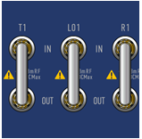
Frequency extension modules connect to additional ports on a configurable front panel: •«Tx» — test receiver input. •«LOx OUT» — Signal output LO (Local Oscillator). •«Rx IN» — reference receiver input. The number in the name (LO1 ... LO4, R1 ... R4, T1 ... T4) associates the additional port with the Test Port number. |