In the basic mode, the function is selected from a limited list of preset functions, and the number of arguments is also limited.
Step-by-step Setup of the Basic Mode
1.Select an active channel and an active trace, in which the calculator trace will be displayed after the calculation.
2.Turn on the calculator (see Turning on the calculator).
3.Select a predefined function from the list.
4.Select the type of operands - parameters or traces.
5.Select the required operands from the list.
6.Click the OK or Apply button to calculate the selected function. By clicking the Apply button, the calculator trace is calculated and drawn using the current measurement data. Clicking OK does the same thing but closes the calculator window.
note |
The active trace is transformed into a calculator trace when the user clicks Apply or OK. Any changes to operands and formulas in the calculator window are not drawn on this trace until this point. If the active trace is already a calculator trace, then the changes the user makes are applied to the calculations immediately and are drawn in real time on the calculator trace. When changing the active trace, the changes are not saved unless the Apply or OK buttons are clicked after making the changes. |
The calculator turns on in basic mode (see figure below). The purpose of the calculator window items is described in the table below.
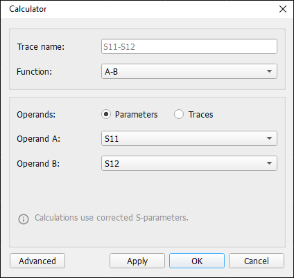
Basic Calculator Mode
Calculator Window Items
Item |
Description |
|---|---|
Trace name field |
Name of the calculator trace. By default, the Trace Name field is identical to the name of the operands and function used and is displayed in gray (see the figure above). If necessary, the field can be edited. |
Function list |
List of a predefined set of mathematical functions (see next table below). |
Operand area |
Selecting the type of operands - Parameters or Traces. The area contains the lists Operand A, Operand B for assigning a specific value to each operand. Additional fields corresponding to the selected function also appear in this area: k1, k2, k3, Offset Amplify, Offset Phase, Number of averaged frames, Scope dB/range, Slope deg./range, IN DUT, OUT DUT. A system information message is displayed below the input fields for the user. An explanatory message appears when an error occurs. |
Apply softkey |
Activating the entered operands and functions to calculate the calculator trace, which will be displayed in the channel window. The calculator trace is then updated as new data arrives. |
OK softkey |
Activating the entered operands and functions to calculate the calculator trace, which will be displayed in the channel window. The calculator trace is then updated as new data arrives, and the calculator window is closed. |
Cancel softkey |
Excluding from the calculation changes, that were made after clicking the Apply button. |
Advanced softkey |
Switch to the advanced mode (see Advanced mode). |
Predefined Basic Mode Functions
Function |
Data source |
Formula |
Description |
|---|---|---|---|
A-B |
S-parameters, trace |
|A-B| |
The modulus of the difference between two traces or two S-parameters. |
A*B |
S-parameters, trace |
A*B |
The product of two traces or two S-parameters. |
A/B |
S-parameters, trace |
A/B |
The quotient of two traces or two S-parameters. |
k1*A + k2*B + k3 |
S-parameters, trace, coefficients k1, k2, k3 |
k1*A + k2*B + k3 |
A weighted sum of two traces or two S-parameters. Various combinations of k1, k2, k3 allow you to create simple expressions. |
Offset |
S-parameters, offset amplify (dB), offset phase (deg.) |
For complex trace: , where P1 – offset amplify [dB] P2 – offset phase [deg.] |
Offset (multiplying parameters by set constants). Not applicable for traces. Select an option and set the amplitude and phase offset coefficients. |
Standard deviation |
S-parameters, number of averaged frames |
– |
Standard deviation (SD) of the parameter at each measurement point. For complex diagrams, only the SD of the modules of complex numbers is calculated, and the phase SD is not calculated. Select a parameter and set the number of sweeps (frames). |
Trend dB |
S-parameters, offset amplify (dB), slope (dB/range) |
For complex trace: , where P1 – offset amplify [dB] P2 – slope [dB / sweep range] N – number of measuring points |
Compensation of the parameter amplitude trend. Does not apply to traces. Select a parameter and specify two coefficients: offset amplify (dB) and slope (dB/range). |
Trend Phase |
S-parameters, offset phase (deg.), slope (dB/range) |
For complex trace: , where P1 – offset phase [deg.] P2 – slope [deg. / sweep range] N – number of measuring points |
Compensation of the parameter phase trend. Not applicable for traces. Select a parameter and specify two coefficients: offset phase (deg.) and slope (deg./range). |
Stability Factor K |
IN DUT (Port n), OUT DUT (Port m) |
, where
|
Stability Factor K (Rollett stability factor). Match the input and output of the DUT to the analyzer port numbers. The condition of unconditional stability is achieved when К>1 and |Δ|<1. |
Stability Factor B1 |
IN DUT (Port n), OUT DUT (Port m) |
, where
|
Stability Factor B1. Match the input and output of the DUT to the analyzer port numbers. A necessary and sufficient condition for stability is: K > 1 and B1 > 0. |