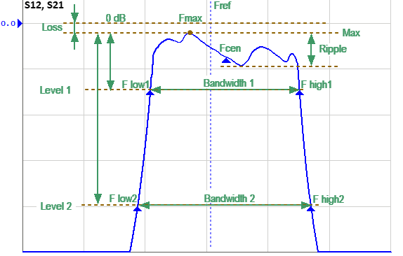
The function measures a number of band pass filter parameters (See figure below).
Bandpass Filter Analysis
Filter Parameters
Parameter Description |
Symbol |
Definition |
Source, formula |
|---|---|---|---|
Reference frequency |
Fref |
Nominal center frequency of the filter. |
Custom setting |
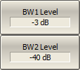
Level 1 |
lvl |
Attenuation from the maximum transmission coefficient to determine the main bandwidth of the filter, default -3 dB. |
Custom setting |
Level 2 |
Attenuation from the maximum transmission coefficient to determine the second bandwidth of the filter for shape factor calculation, default -40 dB. |
Custom setting |
|
Low cutoff frequency |
F low |
Low cutoff frequency for the corresponding Level. |
Automatic search |
High cutoff frequency |
F high |
High cutoff frequency for the corresponding Level. |
Automatic search |
Bandwidth |
BW |
Bandwidth for the corresponding Level. |
Bandwidth 1 = F high1 – F low1 Bandwidth 2 = F high2 – F low2 |
Center frequency |
Fcen |
Actual filter center frequency. |
Fcen = (F high1+F low1) / 2 |
Maximum frequency |
Fmax |
The frequency corresponding to the maximum transmission coefficient of the filter. |
Automatic search |
Frequency difference |
ΔF low ΔF high ΔFcen ΔFmax |
Difference of the corresponding frequency from the nominal center frequency. Can be displayed instead of absolute frequency values. |
ΔF low1 = F low1 - Fref ΔF low2 = F low2 - Fref ΔF high1 = F high1 – Fref ΔF high2 = F high2 – Fref ΔFcen = Fcen – Fref ΔFmax = Fmax - Fref |
Loss |
loss |
Filter loss at Fmax. |
Automatic search |
Quality factor |
Q |
The ratio of the Center frequency to the Bandwidth 1. |
Q = Fcen / Bandwidth 1 |
Shape factor |
SF |
Shape factor of the filter. |
SF = Bandwidth 2 / Bandwidth 1 |
Ripple |
rpl |
Bandwidth ripple value. Defined as the difference between the maximum and local minimum of the filter transmission coefficient in the main bandwidth. |
Automatic search |
Ripple resolution |
|
Minimum difference to find a local minimum. It cuts off small fluctuation caused by noise. |
Custom setting |
|
To enable/disable bandpass filter analysis function, use the following softkeys: Analysis > Bandpass Filter Analysis > Filter Analysis > [ON | OFF] |
|
To set the reference frequency value, use the following softkeys: Analysis > Bandpass Filter Analysis > Ref Frequencies |
|
To set the filter bandwidth levels, use the following softkeys: Analysis > Bandpass Filter Analysis > BW1 Level Analysis > Bandpass Filter Analysis > BW2 Level |
|
To change the display of numerical frequency values on the screen (Flow, Fhigh, Fcen, Fmax), use the following softkeys: Analysis > Bandpass Filter Analysis > Display Frequency > [Absolute | Delta] When choosing: •Absolute – absolute frequency value displayed •Delta – displays frequency difference |
|
To set the ripple resolution value, use the following softkeys: Analysis > Bandpass Filter Analysis > Ripple Resolution |
|
|