The TR series Analyzer contains a vector voltmeter (VVM) function designed to replace the traditional vector voltmeter in measurements. This function allows measuring the raw vector (amplitude and phase) data at a single CW frequency, as well as the ratio of modules and the phase difference of the signals between the two measurement ports (A/B or B/A measurement). The most common practical application of this feature is where many cables must be matched for identical phase shift versus frequency.
When using a VVM function, the absolute values of the measured amplitude and phase can be obtained. Measurements can also be performed relative to the stored data. The Analyzer can store a measurement from a reference cable or component and make further measurements on other similar components to determine the consistency of the components to one another. Saving a reference normalizes the results to the current measurement.
note |
A distinction should be made between the terms "Relative measured values" and "Absolute measured values" referred to in this section with the terms "Relative measurements of S-parameters" and "Absolute measurements". In this section "Relative measured values" are amplitude and phase measurements normalized to a reference value in memory or a reference receiver. "Absolute measured values" are amplitude and phase measurements without normalization. "Relative Measurements" are VVM measurements performed with normalization. |
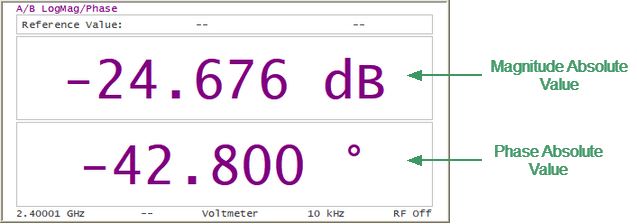
Vector Voltmeter Display
The analyzer's VVM function also provides additional capabilities not available with the traditional VVM:
•The Analyzer has a source and couplers built-in therefore it can measure reflection or transmission of a DUT directly without additional external items.
•Voltmeter data table allows to store measurement data from multiple DUTs and compare them to a reference response.
In practice, the VVM function is especially useful for measurements in systems where cable lengths must have a precise phase relationship to each other. For example, in phased array antennas.
The analyzer provides four types of measurements with the Vector Voltmeter:
•S11 — one-port reflection measurement using the built-in source and couplers.
•S21 — two-port transmission measurement using the built-in source and couplers.
•A/B — ratioed receiver measurement using external source.
•B/A — ratioed receiver measurement using external source.
S11 Reflection Measurement (One-port Method)
This method is used to validate the proper electrical length of any low loss (< 20dB) DUT, such as when accurately trimming a cable according to a reference sample.
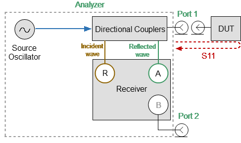
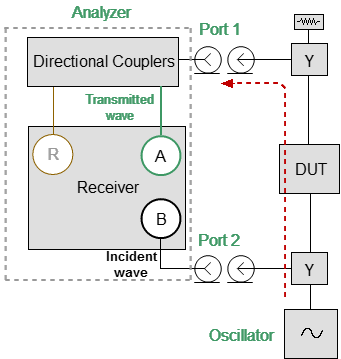
The block diagram of the measuring setup in the reflection measurement mode is shown in the figure below. The R receiver measures the incident signal out of the source. The A receiver measures the reflected signal from the end of the DUT. Ratio (A/R) calculation allows determining the phase shift of the DUT or cable.
Nearly all of the energy in the input signal is reflected off the end of the unterminated cable. The cable measured return loss is twice the one-way loss. The phase shift of the measured reflected signal is equal to twice the one-way phase shift of the cable.
When absolute magnitude and phase are measured, a full one-port calibration (SOL) is used to ensure accurate results. If the relative value of amplitude and phase is being measured, no calibration is required.
Reflection Measurement
Example
Trimming a cable using this method:
•An unterminated reference cable is connected to Port1 and measured. The Analyzer allows saving the measurement of the reference cable as a reference value, then measurements of untrimmed cables will be compared with it.
•Remove the reference cable from Port1 and connect an unterminated untrimmed cable. Carefully trim the cable until the phase shift reads zero. The attached cable’s electrical length is now matched to the reference cable.
NOTE |
The electrical length of the untrimmed cable must be within 180° of the reference cable because the displayed phase changes within ±180°. |
S21 Transmission Measurement (Two-port Method)
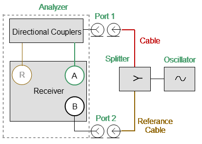
This method is used to measure the electrical length of DUTs with high losses (>20 dB) as it has a high dynamic measurement range for them. The analyzer's signal source is transmitted out the Port1, through the DUT, and into Port 2.
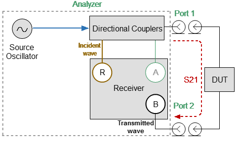
The block diagram of the measuring setup in the transmission measurement mode is shown in the figure below. The R receiver measures the incident signal out of the source. The B receiver measures the signal transmitted through the DUT. Ratio (B/R) calculation allows determining the phase shift of the DUT or cable.
A positive amplitude value represents the gain of the DUT, a negative value represents the loss of the DUT. The phase value is the difference in phase between Port1 and Port2.
Transmission Measurement
When absolute magnitude and phase are measured, a one-path two-port calibration is used to ensure accurate results. If the relative value of amplitude and phase is being measured, no calibration is required.
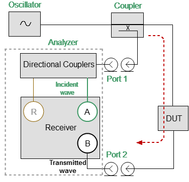
A/B or B/A Measurements
This mode is used in the measurement setup that requires the external CW frequency oscillator and accessories. In this mode, the Analyzer replaces the traditional vector voltmeter. Receivers A and B are used to make relative measurements. One of the receivers (A or B) that measures the signal applied to the DUT is the reference and the other measures the DUT response.
The block diagrams of various measurement setups in B/A and A/B measurement mode is shown in the figures below.
B/A Measurements
A/B Measurements
Vector error correction is not available for A/B or B/A measurements. Measurement results can be improved by adding 3dB or 6dB attenuators to each measurement port (A and B) if the measured results are unstable or unreliable. The reference value is retained after adding attenuators.
Relative Measurements Procedure
1.Set the CW frequency, measurement type and format. The following measurement format can be selected:
•Logarithm Magnitude/Phase
•Linear Magnitude/Phase
•SWR
•Impedance
The measurement format can be changed at any time. If the reference value was saved in a specific format, when the format is changed, the reference value is automatically converted to the new measurement format.
2.No vector error correction is required for relative measurements.
3.Connect the first DUT. If this is a reference DUT, save its measurement value as a reference.
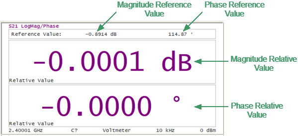
4.After saving the reference value, the measured data display changes (See figure below):
•The reference value is displayed at the top of the voltmeter display.
•Instead of measured absolute values, relative values are displayed, which are the difference between the current measurement and the stored reference value (normalized data).
Relative Measurements Display
5.Next, the DUTs are measured, which are to be compared with the reference DUT. The DUTs are measured sequentially, one after the other. Their relative measurement results will be based on the stored reference value.
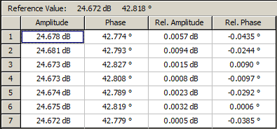
6.For ease of use, measurement values can be displayed as a table. After saving the reference value, both absolute and relative measured values will be presented in the table.
Voltmeter Data Table
7.The reference value stored in memory can be changed or cleared. Clear the reference value memory using the Clear Reference softkey. When the current measurement is desired as the new reference value, use the Save Reference softkey.
8.Clearing the reference value while using the table view will clear all of the relative measurement values in the table. After saving the new reference value, the relative measurement values will be recalculated and displayed relative to the new reference value.
Selection VVM Mode
|
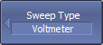
To select VVM mode, use the following softkeys: Stimulus > Sweep Type > Voltmeter |
|
|
Type of Measurement
|
To open VVM submenu, use the following softkeys: Stimulus > Vector Voltmeter |
|
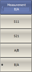
To select the type of measurement, use the following softkeys: Stimulus > Vector Voltmeter > Measurement > [S11 | S21 | A/B | B/A] Where: •S11 — one-port reflection measurement •S21 — two-port transmission measurement •A/B — ratioed receiver measurement (Port1/Port2) •B/A — ratioed receiver measurement (Port2/Port1) |
|
|
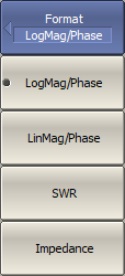
Format
|
To select the format of measurement, use the following softkeys: Stimulus > Vector Voltmeter > Format Then select the required format: •LogMag/Phase •LinMag/Phase •SWR •Impedance |
|
|
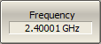
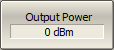
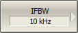
Measurement Conditions
|
To set CW frequency, use the Frequence softkey. |
|
Output power is set for S11, S21 measurements. To set output power, use the Output Power softkey. |
|
To set the IF bandwidth, use the following softkeys: Stimulus > Vector Voltmeter > IF Bandwidth Then select the desired IF bandwidth by the corresponding softkey. |
|
|
Reference Value
|
To store a reference value from current measurements, use the Save Reference softkey. |
|
To clear the reference value memory, use the Clear Reference softkey. |


|
|
Voltmeter Data Table
|
To open Voltmeter Data Table submenu, use the following softkeys: Stimulus > Vector Voltmeter > Voltmeter Data Table |
|
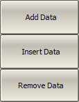
To add data to the last row of a table, use the Add Data softkey. To add data to a selected table row, use the Insert Data softkey. To delete a table row, use the Remove Data softkey. |
|
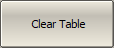
To completely clear the table, use the Clear Table softkey. |
|
To save table data to CSV file, use the Save Table to CSV softkey. Enter the file name in the dialog that appears. |


|
|
Properties
|
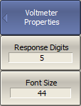
To set Vector Voltmeter properties, use the following softkeys: Stimulus > Vector Voltmeter > Properties Then set the following parameters, use the following softkeys: •Response Digits NOTE By default, the response values are displayed with 5 decimal points. These settings can be changed from 3 to 12. •Font Size NOTE The font size of the response value can be changed to any size between 8 to 72 (default 44). |
|
|