A Vector Network Analyzer (VNA) is a tool for accurate measurement of complex transmission and reflection coefficients (S-parameters) of a Device Under Test (DUT).
The Analyzers described in this manual are USB VNAs. These VNAs consist of an RF measurement module (Analyzer) and supplied processing software — an application which runs on a Windows or Linux based PC or laptop, connected to the Analyzer’s hardware via a USB interface. This application controls the RF measurement module, receives and post-processes received raw data and presents the calibrated results to the user in a variety of graphical formats.
For a detailed description of different models of Analyzers see Instrument Series.
The complete specification and supported features list are given in the datasheet of the corresponding Analyzer
The block diagram of the Analyzer is represented in figure below.
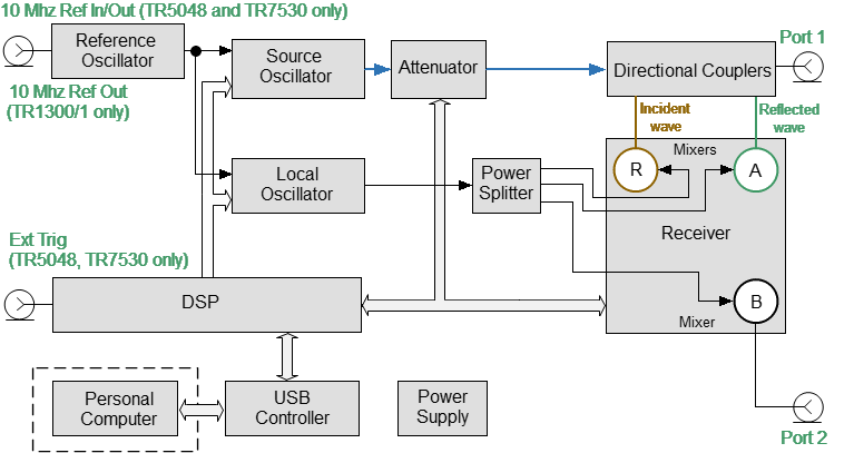
The Block Diagram of the Analyzer
The Analyzer consists of the following functional blocks: a Reference Oscillator, a Source Oscillator, a Local Oscillator, a power control Attenuator, a Power Splitter, Directional Couplers, a three-channel Receiver, a digital signal processor (DSP), a USB Controller and a Power Supply.
A tunable Source Oscillator is the test signal source. The Source Oscillator is based on digital frequency synthesizers. This provides a wide frequency range, set frequency step, and necessary stability for the test signal.
An internal Reference Oscillator provides the Source Oscillator with a stable reference signal.
The Local Oscillator (LO) generates signals using digital frequency synthesizers at an offset from the Source Oscillator which is equal to the Intermediate Frequency (IF) which will be digitized by the VNA IF circuit. The Local Oscillator is the source of the LO signal for the mixers of receiver.
The Power Splitter distributes the LO signal between the three Mixers.
A programmable Attenuator controls the power level of the test signal. This Attenuator is an executive unit of the automatic power control system. For example, when a power calibration has been completed, the Power Correction function uses this Attenuator. Also, the Analyzer can sweep over the output power range at a fixed frequency of test signal using this Attenuator. The user controls the Attenuator by setting the signal power level at the output of the test port. For the power sweep mode, the user sets the range of signal power levels at the output of the measurement port.
After the Attenuator, the test signal passes through the Directional Couplers to Port 1 of the Analyzer. Port 1 is the source of the test signal. The test signal from the signal source goes through the DUT to the connector of the port 2. Port 2 is the receiver of the test signal.
Directional Couplers separate the incident wave and reflected wave of the test signal. The signals from the directional couplers and the signal from the receiver port 2 are supplied into the mixers, where they are converted into first IF 0.3125 MHz (TR5048, TR7530) or 5.037 MHz (TR1300/1), and are transferred further to the 3-Channel receiver:
•The reference receiver R processes the incident wave.
•A measuring receiver A processes the reflected wave.
•A measuring receiver B processes the signal transmitted through a DUT to Port 2.
The 3-Channel receiver, after filtration, produces the signal of the second IF, then digitally encodes it and supplies data into the DSP. The DSP performs primary signal processing (filtering, phase difference estimation, magnitude measurement). The user-selected Bandwidth of the second IF is applied by the DSP filter and has a passband from 10 Hz to 30 kHz.
After the primary signal processing, the DSP transmits the information to the control software (TRVNA) running on an external PC. Communication is provided by a USB controller. This software performs the final signal processing and displays the measurement results on the screen of the PC.