note |
The availability of this feature depends on the Analyzer model (See corresponding datasheet). |
Time domain gating is a function that mathematically removes unwanted responses in the time domain. The function performs a time domain transformation, selects the region in the time domain, deletes the response inside (or outside) the selected region and transforms back to the frequency domain. The function allows the user to remove spurious effects of the fixture in the frequency domain, if the useful signal and spurious signal are separable in the time domain.
The recommended procedure is as follows:
•Use the time domain function for viewing the layout of useful and spurious responses.
•Enable the time domain gating and set the gate position to remove as much of spurious response as possible.
•Disable the time domain function and view the response without spurious effects in frequency domain.
The function involves two types of time gate:
•Bandpass — removes the response outside the time gate span.
•Notch — removes the response inside the time gate span.
The sharp gate shape leads to ringing effect in the frequency domain. To reduce the ringing the gate shape can be smoothed. The following gate shapes are offered:
•Maximum
•Wide
•Normal
•Minimum
The minimum window has a sharp shape. The maximum window has a more smoothed shape. From minimum to maximum window shape, the sidelobe level increases and the gate resolution decreases. The choice of the window shape is always a trade-off between the gate resolution and the level of spurious sidelobes. The parameters of different window shapes are represented in the table below.
Window Shape |
Bandpass Sidelobe Level |
Gate Resolution |
|---|---|---|
Minimum |
– 48 dB |
|
Normal |
– 68 dB |
|
Wide |
– 57 dB |
|
Maximum |
– 70 dB |
|
DUT Low Pass Settings
The Time Domain Gating function has a setting to distinguish between the frequency lowpass DUT and the frequency bandpass DUT. The lowpass DUTs can operate with DC current such as cables or lowpass filters. The bandpass DUTs cannot operate with DC current such as band pass filters or high pass filers.
When the DUT Low Pass setting is OFF:
•The gating function makes no assumption about the DUT response at DC.
•The frequency settings can be arbitrary.
When the DUT Low Pass setting is ON:
•The value of the DUT response at DC is required to be known to the gating function.
•The frequency settings are required to be a harmonic frequency grid, where the frequency value at each frequency point is an integer multiple of the start frequency.
The DC value cannot be measured directly by the Analyzer. The Analyzer offers two options: the DC value is automatically extrapolated or manually set. The last option is used when the DUT response at DC is well known, for example, for a low loss cable the DC value is:
•"1" for open-ended cable.
•"-1" for a short-circuited cable.
•"0" for a cable terminated with a matched load.
The Analyzer can set the harmonic frequency grid from the current frequency settings with one click.
note |
The following settings of the Gating function: DUT Low Pass ON/OFF, Set Frequency Low Pass, Extrapolate DC and DC value also set the corresponding settings of the Time Domain function (See Time Domain Transformation). |
Time Domain Gate Activation
|
To enable/disable the time domain gating function, toggle the following softkey: Analysis > Gating > Gating [ ON | OFF ] |


|
|
note |
Time domain gating function is accessible only in linear frequency sweep mode. |
Time Domain Gate Span
|
To the start and stop of the time domain gate, use the following softkeys: Analysis > Gating > Start Analysis > Gating > Stop |

|
To set the center and span of the time domain gate, use the following softkeys: Analysis > Gating > Center Analysis > Gating > Span |

|
|
Time Domain Gate Type
|
To select the gate type, use the following softkeys: Analysis > Gating > Type Toggle the type between Bandpass and Notch. |

|
|
Time Domain Gate Shape Setting
|
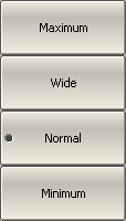
To set the time domain gate shape, use the following softkeys: Analysis > Gating > Shape > [ Minimum | Normal | Wide | Maximum ] |

|
|
DUT Low Pass Setting
|
To select the type of DUT from lowpass or bandpass, use the following softkeys: Analysis > Gating > DUT Low Pass [ ON | OFF ] |

|
|
|
To create a harmonic grid for the current frequency range, use the following softkeys: Analysis > Time Domain > Set Frequency Low Pass |


|
To enable extrapolation of DC values, use the following softkeys: Analysis > Time Domain > Extrapolate DC [ ON | OFF ] |
|
To set the DC value manually, use the following softkeys: Analysis > Time Domain > DC Value |
|
|
note |
The following softkeys: Set Frequency Low Pass, Extrapolate DC, DC Value are duplicated in the Time Domain menu. The settings they make have the same effect on Time Domain and Gating. The DUT Low Pass softkey is related to the Type (of time domain transformation) softkey in the Time Domain menu as follows: •If DUT Low Pass turn ON, Type set to Lowpass [ Impulse or Step ]. •If DUT Low Pass turn OFF, Type set to Bandpass. |