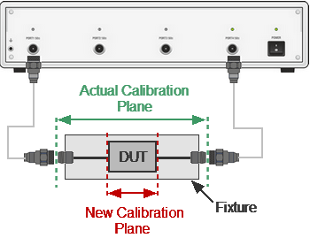
The port extension function moves the calibration plane toward the DUT terminals by the specified electrical delay value. The function is useful when a fixture is used for the DUT connecting and the calibration cannot be performed at the DUT terminals. The calibration plane can be established at coaxial connectors of the fixture and then moved to the DUT terminals using the port extension function (See figure below).
Port extension
The function uses the model of the perfectly matched transmission line with loss with parameters:
•The phase incursion in the line is
,
where - frequency, Hz,
- electrical delay, sec.
•The loss of the line can be specified by one of the following methods:
1.Frequency-independent loss at DC ()
.
2. Loss determined by the losses in two frequency points ( at DC, and at frequency )
3. Loss determined by the losses in three frequency points ( at DC, at frequency and at frequency )
,
.
note |
The accuracy of the port extension method depends on the fixture used. The closer the fixture parameters are to the model of a perfectly matched transmission line, the higher the accuracy. |
|
To enable the port extension function, use the following softkeys: Calibration > Port Extensions > Extensions [ ON|OFF] |


|
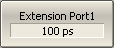
To set the electrical delay for each port, use the following softkeys: Extension Port n |
|
To open the menu of the losses, use the following softkeys: Calibration > Port Extensions >Loss |
|
To select the port in menu, use softkey: Select Port |
|
Enter the , values and enable the use of these values in further calculations, use the following softkeys: Loss1 [ ON | OFF ] Loss1 Freq1 Perform the same steps for , . |
|
Enter the value, use the following softkey: Loss at DC |


|
|