Balance-unbalance conversion simulates measurements in the balanced circuits using the results of unbalanced measurements. This allows evaluating balanced parameters of balanced devices. The diagram of balance-unbalance conversion is shown in figure below.
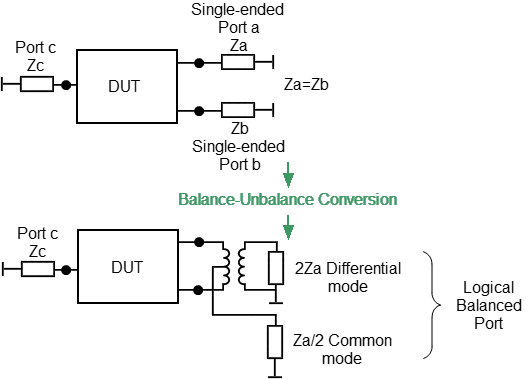
Balance-unbalance conversion diagram
The types of evaluated balanced devices are shown in figures below.

Single ended - Balanced devices (Se-Bal)

Balanced - Balanced devices (Bal-Bal)

Single ended - Single ended - Balanced devices (Se-Se-Bal)

Balanced devices (Bal)
Types of balanced devices
Unlike other fixture simulation functions, the balance-unbalance conversion function has an active trace and not the whole channel as a target. Before using this function, select the target trace.
|
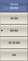
Define the balanced devices topology, use the following softkeys: Analysis > Fixture Simulator > Topology > Device > [SE-Bal | Bal-Bal | SE-SE-Bal | Bal] |
|
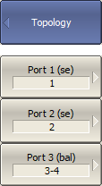
Match the port numbers to the logical (balanced) ports, use the following softkeys: Analysis > Fixture Simulator > Topology > Port 1 (se | bal) Analysis > Fixture Simulator > Topology > Port 2 (se | bal) Analysis > Fixture Simulator > Topology > Port 3 (bal) Then select the Analyzer port numbers connected to the selected logical ports. |
|
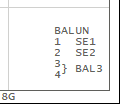
To display the matching numbers with ports, use the softkey: Analysis > Fixture Simulator > Topology > Property [ON | OFF]
|
|
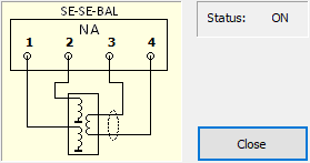
To display the balance-unbalance conversion diagram, use the softkey: Analysis > Fixture Simulator > Topology > Help
|
|
To enable the balance-unbalance conversion function, use the following softkeys: •For active trace: Analysis > Fixture Simulator > BalUn [ON | OFF] •Enable for all traces: Analysis > Fixture Simulator > BalUn ON All Traces •Disable for all traces: Analysis > Fixture Simulator > BalUn OFF All Traces |
|
To select the measured balanced parameter for each trace, use the following softkeys: Analysis > Fixture Simulator > Measurement > [Sdd11 | … CMRR] |
|
|
note |
The set of available balanced parameters depends on the topology selected. See the next section for the detailed description of balanced parameters. |
