Gauging connectors not only provides assurance of proper mechanical tolerances, and thus connector performance, but also indicates when there is potential for causing damage to another connector.
Connector gauging should be performed before the instrument is first used, and during regular operation.
The first gauging of connectors obtains the pin depth, which can be used during operation with the module to evaluate its changes.
Gauge the connectors if:
•the device (instrument, calibration standard, cable, adapter, attenuator, or other RF item with coaxial connectors) is being used for the first time.
•visual inspection of the Analyzer calibration suggests that the connector may have defects or damage.
•the connectors of the device used with the Analyzer are damaged, or their pin depth values are out of the range for this type of connector.
•the device is shared with someone else.
•after every 100 connections or as often as experience suggests.
The procedure for connector gauging is as follows (See figure):
1. Select the proper gauge for your connector.
2. Inspect and clean the gauge, the gauge master, and the connectors to be gauged.
3. Zero the connector gauge before use (according to the gauge documentation).
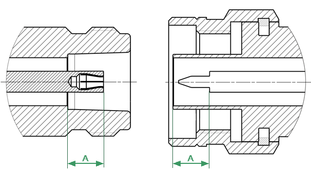
4. Gauge the connector: while holding the gauge by the barrel, carefully connect the connector under test to the gauge. Read the gauge indicator dial value to determine recession or protrusion and compare the readings with the device specifications (See the figure and table below).
Note |
Use multiple measurements and keep records of readings. |
Note |
Never use an out of specification connector. Do not hold connector gauge by the dial. |
|
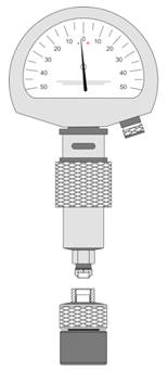
|
Gauge Master, male |
Connectors, male |
|
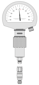
|
Gauge Master, female |
Connectors, female |
Example of Gauging Connectors |
|
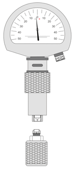
|
Type-N Connectors (female and male) |
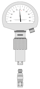
|
3.5 mm NMD Connectors (female and male) |
Mechanical Requirements for Measured Connectors |
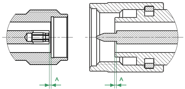
The А pin depth value of connector
Connector type |
А pin acceptable depth range |
|---|---|
Type-N, female |
5.18 to 5.26 mm |
Type-N, male |
5.28 to 5.36 mm |
2.4 mm NMD, female 3.5 mm NMD, female |
-0.08 to 0.00 mm |
2.4 mm NMD, male 3.5 mm NMD, male |
-0.08 to 0.00 mm |
If the pin depth values of the gauged connectors are out of the acceptable range, the connectors may be eligible to be sent in for repair.