This section is organized as a sample session of the Analyzer. It describes the main techniques for measurement, for example, measuring the reflection coefficient parameters of the DUT. SWR and reflection coefficient phase of the DUT will be analyzed.
In this example, only one test port of the Analyzer is used for reflection coefficient measurement. The instrument sends the stimulus to the input of the DUT and then receives the reflected wave. If the DUT is a two-port device, its unused port should be terminated with a LOAD standard. The results of these measurements can be represented in various formats.
A typical setup for reflection coefficient measurement is shown below.
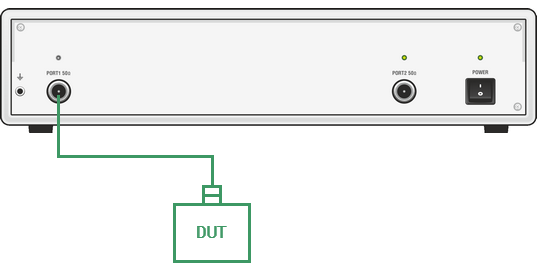
Reflection Measurement Circuit
To measure SWR and reflection coefficient phase of the DUT in the given example, go through the following steps:
•Prepare the Analyzer for reflection measurement.
•Set stimulus parameters (frequency range, number of points).
•Set IF bandwidth.
•Set the number of traces to 2, assign measured parameters and display format to the traces.
•Set the scale of the traces.
•Perform a one-port calibration.
•Analyze SWR and reflection coefficient phase using markers.
note |
The Analyzer can be controlled via softkey panel located on the right-hand part of the screen. The analyzer also allows to perform quick control by the mouse (See Quick Setting Using a Mouse). |