Advanced Series models deliver lab grade performance, with all the features engineers have come to expect included standard in software.
The front view of the Analyzers is represented in the figures below.
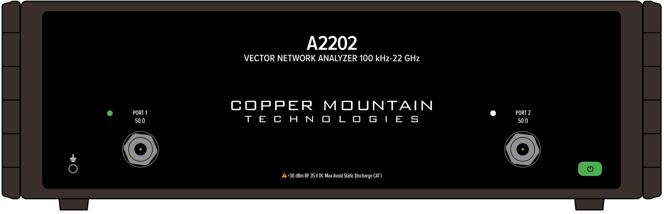
A2202 Front Panel
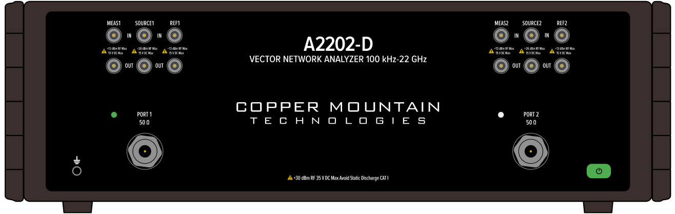
A2202-D Front Panel
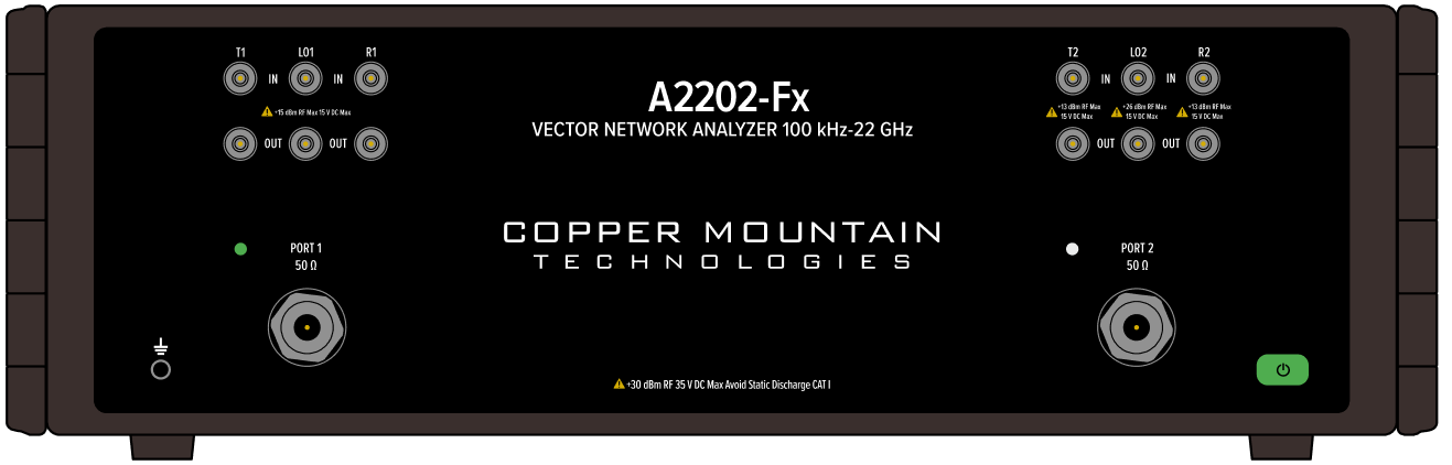
A2202-Fx Front Panel
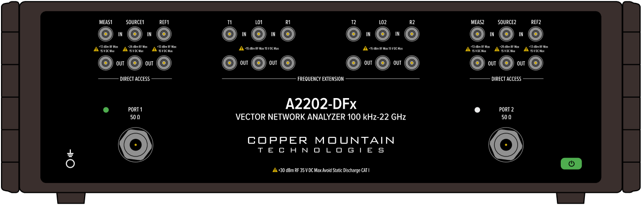
A2202 Front Panel
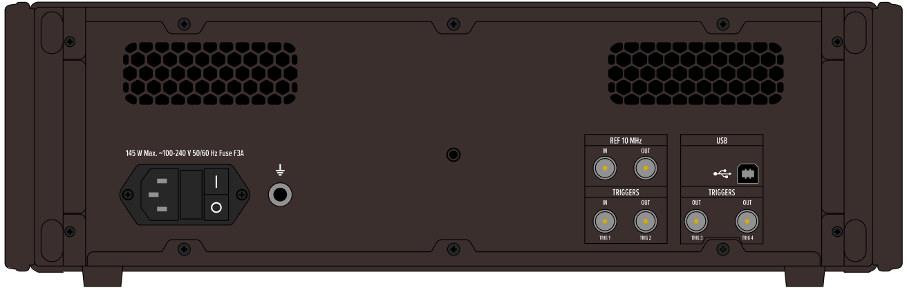
A2202/A2202-D/A2202-Fx/A2202-DFx Rear Panel
Parts of front panel
Power Button
|
Switches the Analyzer ON and OFF. The Analyzer can be turned ON/OFF at any time. The VNA loads its operating firmware from the PC each time upon powering up. The process will take approximately 10 seconds, after which the Analyzer will be ready for operation. |

note |
The USB driver will be installed onto the PC when the Analyzer is turned ON for the first time. The driver installation procedure is described in Software Installation. Some PCs may require re-installation of the driver in case of change of the USB port. |
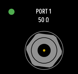
Test Ports
note |
The LED indicator identifies the test port which is operating as a signal source. |
Caution |
Do not exceed the maximum allowed power of the input RF signal (or maximum DC voltage) indicated on the front panel. This may lead to damage of the Analyzer. |
Ground Terminal
|
Use the terminal for grounding. To avoid damage from electric discharge, connect the ground terminal on the body of the Analyzer to a reliable earth ground shared with the DUT in the test environment. |

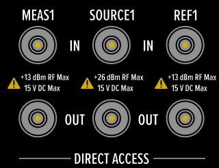
Direct Receiver Access (A2202-D & A2202-DFx Only)
|
One set of Measure, Source, and Reference IN/OUT ports for each test port. |
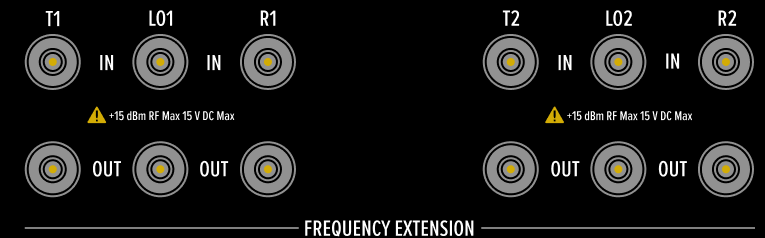
Frequency Extension (A2202-Fx & A2202-DFx Only)
|
One set of transmission, LO, and reflection IN/OUT ports for each test port. |
Parts of rear panel
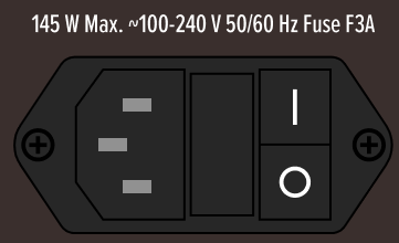
Power Cable Receptacle
|
The power supply receptacle is intended for an external DC power supply voltage from 100-240 V. 145 Watt max, 50/60 Hz fuse. |
Ground Terminal
|
To avoid electric shock, use this terminal for grounding. The Ground terminal allows to directly connect the body of the Analyzer to the test station ground in order to ensure electrical safety. |
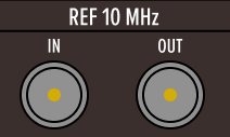
Reference Input/Output
|
External reference frequency is 10 MHz, 0 to 2 dBm. Connector type BNC female. Internal reference frequency is 10 MHz, -2 to 4 dBm. Connector type BNC female. |
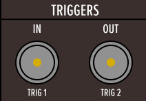
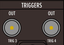
Trigger Input/Output
|
External trigger input and output. Connector type is BNC female. For input and signal parameters, see instrument specifications. |
Trigger Input/Output
|
USB connector, type B USB 2.0. |