note |
This section is available for R60, R140B and R180. |
This section describes settings of the trigger output. The trigger output is designed to synchronize external devices with the analyzer measurement cycle.
The user can use TRIG IN/OUT or REF 10 MHZ/TRIG OUT connector to output a logic signal from the analyzer (See figure below). The table below shows possible ways of use for the analyzer connectors.
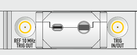
External Trigger Output Connector R60 and R180
Functions of the TRIG IN/OUT or REF 10 MHZ/TRIG OUT analyzer's connectors
TRIG IN/OUT |
REF 10 MHZ/TRIG OUT |
|---|---|
trigger input |
trigger output or reference source input or reference source output |
trigger output |
reference source input or reference source output |
To use the TRIG IN/OUT connector to output a logic signal:
•Select trigger source Internal or Bus (See Trigger Source).
•Turn on trigger output (See Enabling Trigger Output).
•Set the polarity of the trigger (See Trigger Output Polarity).
•Select the trigger signal condition (See Trigger Output Function).
To use REF 10 MHZ/TRIG OUT connector to output a logic signal :
•Select trigger source External (See Trigger Source).
•Turn on trigger output (See Enabling Trigger Output).
•Set the polarity of the trigger (See Trigger Output Polarity).
•Select the trigger signal condition (See Trigger Output Function).