note |
This section is available for RNVNA. |
Analyzers’ internal reference generators have the finite frequency accuracy. When working with several Analyzers in Internal frequency synchronization mode (See RNVNA Reference Source) the output frequency of each of Analyzer must be set relative to the Analyzer designated as port 1 (See Connecting devices to a USB port). This eliminates the error in the measurement of the transmission coefficients due to frequency of a single Analyzer not falling in the bandwidth of the filter of another Analyzer.
To measure the module of the transmission coefficient, the reference frequencies of the analyzers should be the same. A small error in setting the reference frequencies reduces the measurement accuracy. A mismatch of the reference frequencies when measuring the module of transmission coefficient leads to a deviation of the signal source from the frequency of the signal receiver. This may result in the signal being received by the analyzer receiver with the significant attenuation or not being received at all.
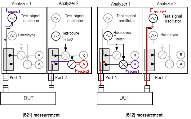
Measuring the S-parameters of the DUT without adjusting the oscillator frequency
The internal reference oscillators of analyzers have the limited frequency accuracy. Therefore, if the analyzers use their own reference frequency oscillators (the reference frequency source is set to Internal, see section Reference source setting), use the frequency adjustment function of the internal oscillators. The frequency adjustment of each analyzer is performed relative to the first device in the list (the analyzer to which port 1 is assigned, see section Connecting devices to a USB port). This is done in order to eliminate the error in measuring the modules of the transmission coefficients connected with the frequency offset of one of the analyzers and not falling into the IF filter bandwidth of the other (see the figure below).
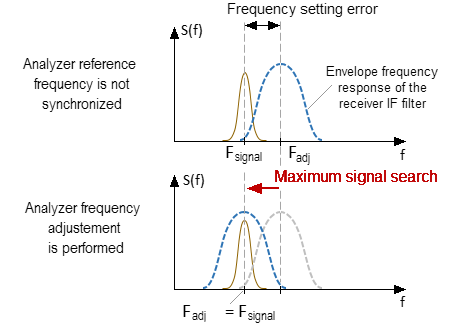
Analyzer frequency adjustment
NOTE |
In case of External or Linked frequency synchronization mode is selected, manual frequency tuning is not required. The value of the frequency offset in this case is indicated as 0. If the reference frequency inputs of two analyzers are connected to each other with a coaxial cable and the reference frequency source is selected as External or Linked, frequency adjustment is not required. The amount of frequency adjustment in this case is assumed to be zero. When selecting Linked as a frequency reference source, the device uses a common frequency reference bus, in this case the first device is the source and the others are the receivers. |
In the software it is possible to perform:
•periodic automatic adjustment of the frequency offset (with a specified start period);
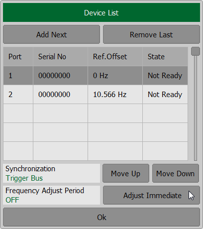
•one-time automatic adjustment of the frequency offset (performed by clicking a button);
•manual frequency offset adjustment.
By default, adjustment automatically starts to work when Analyzers are connected to the software. The parameters of the automatic adjustment and its periodicity can be specified by the user.
When performing the frequency adjustment, ports of the Analyzers should be connected together directly or via DUT. It is necessary to ensure the attenuation of the signal propagation between ports is not more than 50 dB.
The tuning is performed on the central frequency of the specified frequency range of active channel.
The Analyzer should be warmed up before measuring in order to minimize the temperature drift of reference generators.
Manual frequency adjustment
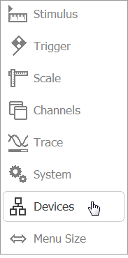
To perform manual frequency adjustment, click the Devices softkey. Click the adjustable port field in the Ref. Offset column in the table and enter the frequency value in the window that opens.
|
Automatic frequency adjustment
In the automatic frequency adjustment mode, the software performs the adjustment in a specified time interval. The real interval of the adjustment can be longer than specified.
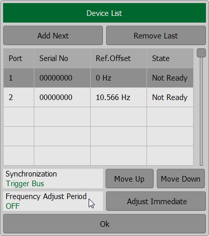
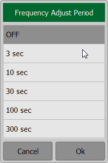
To perform automatic frequency adjustments, press the softkey Devices and click the left mouse button on the field Frequency Adjust Period. In dialog window Frequency Adjust Period select the time interval and press Ok softkey.
|
