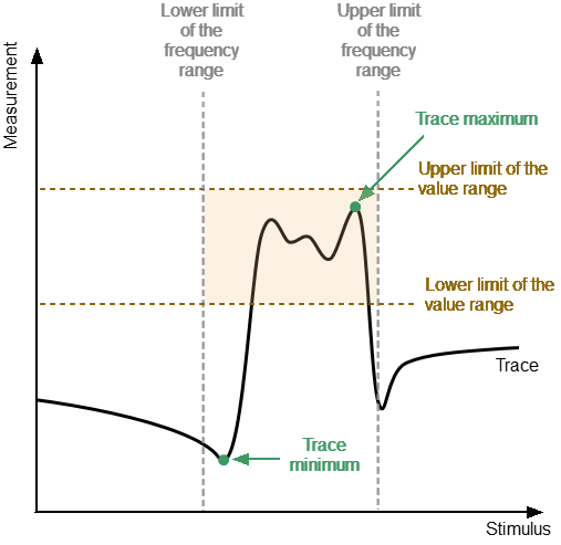
The peak limits test function checks whether the trace point with the minimum (or maximum) value of the measured value falls within the specified limits of the frequency range and/or value range (see figure below). If the trace point minimum (or maximum) falls within the specified limits, the test is passed (test result "pass"). Otherwise, the test is failed (test result "fail").
Peak limits test
Peak Limits Test parameter
A description of the parameters of the peak limits test function in the software is shown in the table below.
Parameter |
Definition |
|---|---|
Limit Type |
Selects the type of limit (one of the limits or both at the same time). Possible values: •Stimulus — checks whether the maximum (or minimum) point of the trace is within the specified frequency bandwidth. •Response — checks whether the maximum (or minimum) point of the trace falls within the value range. •All — checks the maximum (or minimum) trace point simultaneously within the frequency band and within the value range of the measured value. |
Begin Stimulus |
Lower bandwidth limit. |
End Stimulus |
Upper bandwidth limit. |
Begin Response |
Lower limit of the value range. |
End Response |
Upper limit of the value range. |
Peak Polarity |
Selects a trace point for inspection: •Positive — trace maximum. •Negative — trace minimum. |
note |
The peak limit test for the Stimulus limit type can only be performed in the frequency domain. |
Peak Limits Enabling/Disabling
|
To enable/disable peak limits test function: Limits > Peak Limits Then use the toggle to turn it ON/OFF. |
Editing Search Parameters for Peak Limits
|
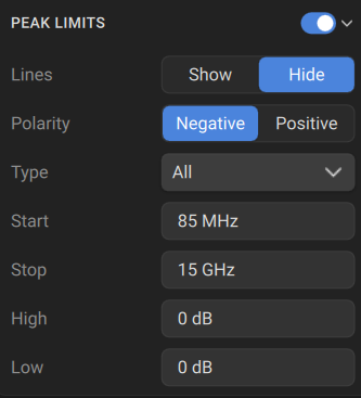
To select the limit type: Limits > Peak Limits > Type Then select the required type: •All •Stimulus •Response |
|
To enter the lower bandwidth limit, use Limits > Peak Limits > Type: All or Type: Stimulus > Start. To enter the upper bandwidth limit, use Limits > Peak Limits > Type: All or Type: Stimulus > Stop. To enter the lower limit of the value range, use Limits > Peak Limits > Type: All or Type: Response > Low. To enter the upper limit of the value range, use Limits > Peak Limits > Type: All or Type: Response > High. |
|
To select a trace point to check, use Polarity [Negative | Positive]. |
Peak Limits Test Display Management
The display of the peak limits on the screen can be turned on/off.
The result of the peak limits test is indicated in the upper right corner of the diagram:
•If the measurement result passed the peak limit test, the trace number and the result will be seen: Tr1: PkLim Pass.
•If the measurement result failed, the result will be indicated in the following ways:
1.Tr1: PkLim Fail will be displayed in upper right corner of the diagram.
2.Fail sign will be displayed in red in the center of the window.