Gauge the connectors before using the Module for the first time, and regularly during operation.
The first gauging of connectors obtains pin depth, which can be used during the Module operation to evaluate its changing.
Gauge the connectors again if:
•A visual inspection or Module calibration results suggest that the connector may have defects or damages.
•The device connectors used with the Module are damaged or their pin depth values are out of range for this type of connectors.
•After every 100 connections.
Use gauges for coaxial connectors in compliance with their operating instructions or use multi-purpose tools for linear measurements (for example, micrometer, dial indicator, etc.) to gauge the connectors.
The pin depth of the connectors “PORT A”, “PORT B” and, if available, “PORT C” and “PORT D” are subject to verification. Only measure the А pin depth of type N connectors and 3.5 mm connectors (See figures below).
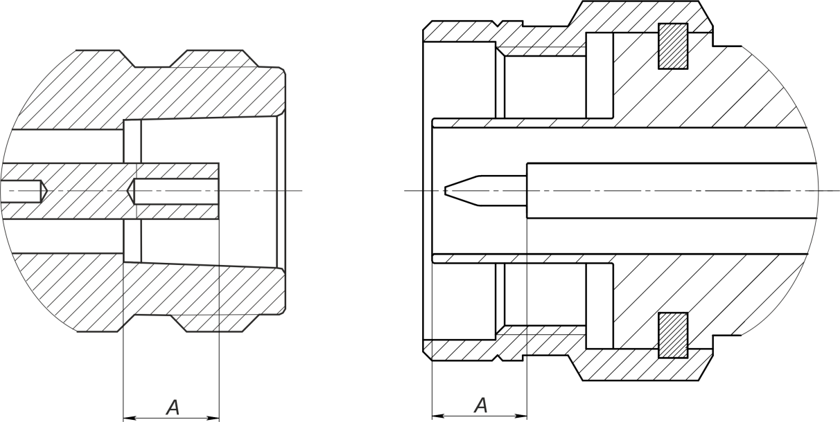
Type N connectors (female and male)

2.4 mm, 2.92 mm, 3.5 mm connectors (female and male)
The А pin depth value of Module ports connectors must be within the following ranges:
Connectors type |
Pin depth range |
|---|---|
Type N, female |
5.18 to 5.26 mm |
Type N, male |
5.28 to 5.36 mm |
2.4 mm, 2.92 mm, 3.5 mm, male |
- 0.08 to 0.00 mm |
2.4 mm, 2.92 mm, 3.5 mm, female |
- 0.08 to 0.00 mm |
The A pin depth value ranges for connectors of other devices are be indicated in their operating manuals.
WARNING |
If the pin depth values of the gauged connectors are out of the specified range, such connectors are subject to repair (See Routine Repairs). A device with such connectors is discarded. |