The Module connectors should be connected in the following order:
1. Fix the housing of one of the devices being connected. This is necessary to avoid its displacement during connection. Fix the device by any of the following ways:
•By clamps or wrenches.
•By weight or configuration of the device itself.
•By holding the device by hand
2. Carefully align the connectors of the connected devices.
3. While holding the device being connected, tighten the male connector nut finger tight. Mating plane surfaces of center conductors and outer conductors have to make uniform light contact as shown in the figures below.
4. Tighten the male connector nut using the appropriate torque wrench (the torque value depends on the connector type), while holding the device being connected manually or by using an open-end wrench to keep it from turning. Finally, tighten the male connector nut by holding the wrench at the end of the handle. Tighten the connection just to the torque wrench break point.
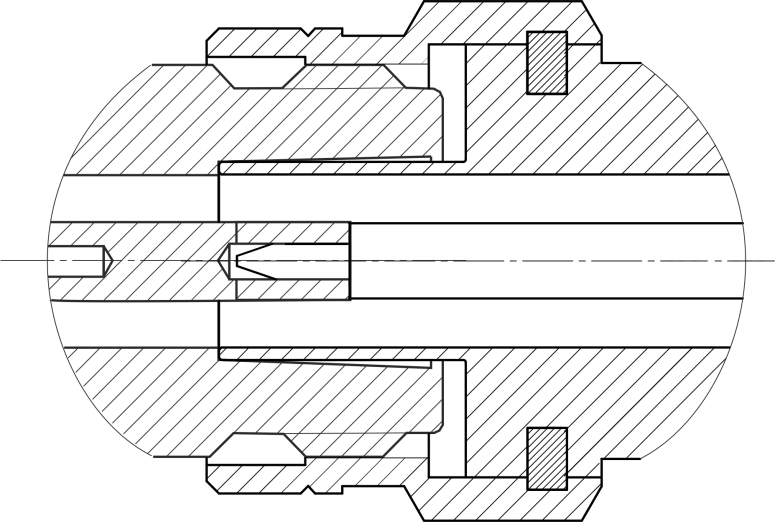
Type N connectors (female on the left, male on the right)

2.4 mm, 2.92 mm, 3.5 mm connectors (female on the left, male on the right)
Disconnect the connectors in the following order:
1. Using the torque wrench, which was used for tightening, loosen the male connector nut, while holding the device by hand or an open-end wrench to prevent it from turning.
2. While holding the device so that the connector’s center conductor was at the same straight line as it was connected, turn the male connector nut. Pull the connectors straight apart.
WARNING |
Do not use alcohol, alkali, or acid for cleaning. |