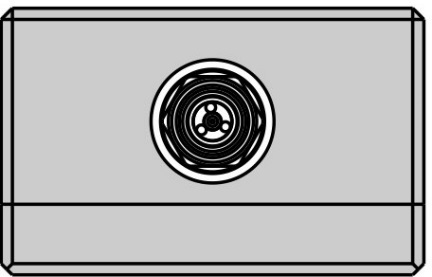
The front panels of the different models of ACM2520 are shown in the figure below.
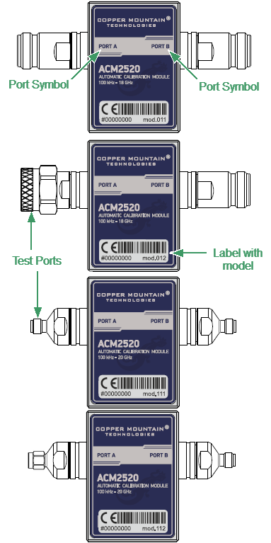
Front panel ACM2520
Parts of Module
Test port
The test ports are designed for connection to VNA being calibrated. The VNA connectors, the cross sections of which were calibrated, are referred to as its test ports.
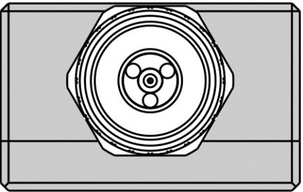
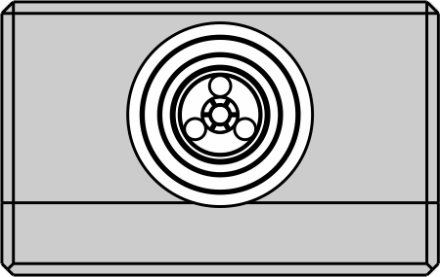
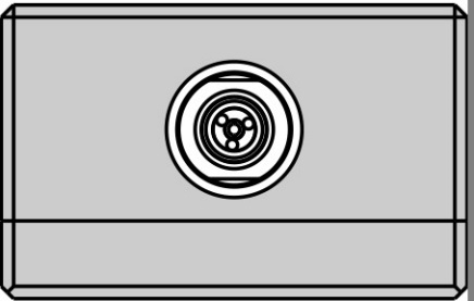
The Modules connectors are shown in figures below.
|
|
Type N, male |
Type N, female |
|
|
3.5 mm, female |
3.5 mm, male |
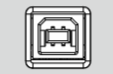
Connector (on side panel)
|
The connector is located on the top of the Module and is intended for the Module connection to the controlling PC. The Module is powered using the USB cable. |
LED Status Indicator (on rear panel)
note |
LED Status Indicator is located under the label and is visible only during operation. |
The LED indicates the following statuses:
•Blinking green and red LED mean testing LED and indicating external power supply voltage presence.
•Red LED indicator means warm-up mode of the Module. The time required for operating mode setting is automatically counted from the moment of the Module connection using USB. If the Module is disconnected during setting and reconnected again, then the countdown counter starts from the beginning.
Additional red LED may indicate the Module connection loss with the PC. In this case, check the Module connection with software (the Autocalibration softkey should be active), if there is no connection, disconnect the USB cable from the Module and repeat the connection.
•Green LED indicator means the Module is ready for operation.
Model |
Connector type |
|
|---|---|---|
Port A |
Port B |
|
ACM2520-011 |
type N, female |
type N, female |
ACM2520-012 |
type N, male |
type N, female |
ACM2520-111 |
3.5 mm, female |
3.5 mm, female |
ACM2520-112 |
3.5 mm, male |
3.5 mm, female |