The frequency offset mode allows for S-parameter measurement of frequency converting devices, including vector reflection measurements and scalar transmission measurements. In this context, frequency converting devices include both frequency shifting devices such as mixers and converters, as well as devices dividing or multiplying frequency.
This measurement mode is based on a frequency offset between the ports. The frequency offset is defined for each port using three coefficients: multiplier, divider, and offset. These coefficients allow for calculation of a port frequency relative to the basic frequency range:
where:
M — multiplier,
D — divider,
— offset,
— basic frequency.
In most cases, it is enough to apply an offset to only one of the ports, leaving the other one at the basic frequency (M=1, D=1, =0).
Below are some examples of offset coefficient calculation for different types of frequency conversion. Here, the mixer RF input is connected to Port 1, and the mixer IF output is connected to Port 2. The basic frequency range is set to the mixer RF frequency range, and the first port of the Analyzer does not use frequency offset. The second port of the Analyzer is set to the IF frequency range and uses frequency offset mode as follows:
1. IF = RF – LO |
Port 2: M = 1, D = 1, = – LO. |
2. IF = LO – RF |
Port 2: M= – 1, D = 1, = LO. |
3. IF = RF + LO |
Port 2: M = 1, D = 1, = LO. |
In frequency offset mode, the bottom part of the channel window will indicate each port’s frequency span (See figure below).
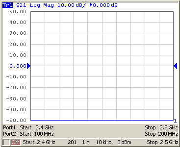
Channel window in frequency offset mode
Start and Stop frequency can be set for each port directly instead of using Multiplier, Divider and Offset values. Using Start/Stop values will set Multiplier and Offset, which can be determined from the specified frequency and the base frequency while maintaining the preset Divider.
Source/Receivers Frequency Offset Feature
Conventional frequency offset mode uses frequency offset between the ports, while the source and receivers of each port operate at a common frequency. Frequency offset between the ports allows for S-parameter measurement of frequency converting devices, including vector reflection measurements and scalar transmission measurements.
The source/receivers frequency offset feature introduces a frequency offset between the source and receivers within a single port. Frequency offset between the source and receivers allows for absolute measurements only.
|
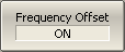
To enable/disable frequency offset mode, use the following softkeys: Stimulus > Frequency Offset > Frequency Offset [ ON|OFF ] |

|
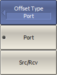
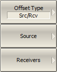
To select the offset type, use the following softkeys: Offset Type > Port or Src/Rcv |
|
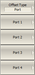
If conventional frequency offset mode uses and Offset Type is set to Port, enter offset coefficients for Ports. |
|
If a frequency offset is introduced between the source and the receivers within a single port and Offset Type is set to Src/Rcv, enter offset coefficients for Source and Receivers. |
|
To enter offset coefficients of multiplier, use the Multiplier softkey. |

|
To enter offset coefficients of divider, use the Divider softkey. |

|
To enter the basic frequency range offset, use the Offset softkey. |
|
To set the start frequency range, use the Start softkey. |
|
To set the stop frequency range, use the Stop softkey. |
|
|