A model of a calibration standard presented as an equivalent circuit is used for determining S-parameters of the standard. The model is employed for standards of OPEN, SHORT, FIXED LOAD, THRU/LINE types.
A one-port model is used for the standards OPEN, SHORT and FIXED LOAD (See Full One-Port Calibration). This is shown in the figure below.
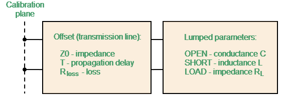
One-port standard model
The two-port model is used for the standard THRU/LINE (See figure below).
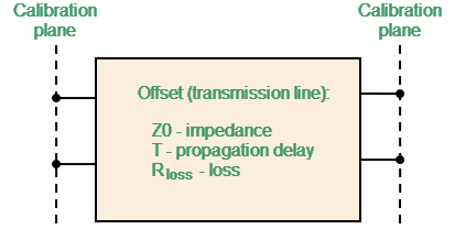
Two-port standard model
The description of the numeric parameters of an equivalent circuit model of a calibration standard is shown in the table below.
Parameters of the calibration standard equivalent circuit model
Parameter (as in the software) |
Parameter Definition |
|---|---|
Z0 (Offset Z0) |
The characteristic impedance of the transmission line [Ω], serving as the offset. For the coaxial line specified real value of characteristic impedance, usually equal to 50 Ω or 75 Ω. For waveguide calibration, the special value of 1 Ω is used. |
T (Offset Delay) |
The offset delay. It is defined as one-way signal propagation time in the transmission line [seconds]. The delay can be measured or mathematically determined by dividing the exact physical length by the propagation velocity in the line. For waveguide, delay is conventionally taken to be equal to the delay of a coaxial line of the same length. The actual signal delay in waveguide is frequency dependent and is calculated in the software. Instead delay, one can specify the length of the offset [meters]. The software calculates the delay according to the formula for a coaxial air line: , where — line length [m], — light speed in free space 299792458 [m/s], — relative permittivity of air 1.000649. The length can be specified instead of the delay provided offset of the calibration standard is a coaxial airline or a waveguide. If the calibration standard manufacturer provides a delay data, it is better to specify delay. Note: When the Multiline TRL calibration is used it is recommended to always specify the length of TRL lines independently of line type, dielectric, presence of propagation speed dispersion. The Multiline TRL uses for calculations physical length of lines. |
Rloss (Offset Loss) |
The offset loss in one-way propagation due to the skin effect [Ω/sec]. The loss in a coaxial transmission line is determined by measuring the delay T [sec] and loss L [dB] at 1 GHz frequency. The measured values are used in the following formula:
The loss in waveguide is typically set to 0 due to its very small influence. However, the software supports a waveguide loss model. If the calibration standard manufacturer provides loss data, it is recommended to specify it. |
Rload (Load Impedance) |
Load impedance of fixed load calibration standard [Ω]. For the coaxial calibration standard specified real value of characteristic impedance, usually equal to 50 Ω or 75 Ω. For waveguide calibration, the special value of 1 Ω is used. |
C (C0, C1, C2, C3) |
The fringe capacitance of an OPEN standard, which causes a phase offset of the reflection coefficient at high frequencies. The fringe capacitance model is described as a function of frequency, which is a polynomial of the third degree: , where — frequency [Hz], C0…C3 — polynomial coefficients. Units: C0[F], C1[F/Hz], C2[F/Hz2], C3[F/Hz3]. |
L (L0, L1, L2, L3) |
The residual inductance of a SHORT standard, which causes a phase offset of the reflection coefficient at high frequencies. The residual inductance model is described as a function of frequency, which is a polynomial of the third degree: , where — frequency [Hz], L0…L3 — polynomial coefficients. Units: L0[H], L1[H/Hz], L2[H/Hz2], L3[H/Hz3]. |
Media |
The offset media. Allows to choose from: •coaxial •waveguide |
Width to Height Ratio (H/W) |
The waveguide width to height ratio. Used in the waveguide loss model when the loss value is not zero. |
Minimum and Maximum Frequency (Fmin, Fmax) |
The minimum and maximum standard operating frequency in the coaxial. Used for a calibration using several calibration standards, each of which does not cover entire frequency range. The cut off frequency and the doubled cut off frequency of the waveguide. The cutoff frequency of the waveguide is achieved at a wavelength in the waveguide equal to twice its width. Take care not to confuse this with the minimum and maximum operating frequency of the waveguide, which are usually given by the manufacturer with a margin relative to the cut off frequency. |