FET1854 frequency extension modules allow for measurement of the DUT S-parameters in the frequency range between 18 to 54 GHz. See the FET Operating Manual for a detailed description of the module.
The front and rear panels of the Module are shown in the figures below. The test port and ground terminal are located on the front panel. The rear panel contains a status indicator, a control cable connector, and a group of connectors for connecting the module to the Analyzer:
•Test signal (RF IN)
•LO signal (LO IN)
•IF signal of the reference channel (IF REF)
•IF signal of the test channel (IF TEST)
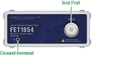
Front panel of FET1854
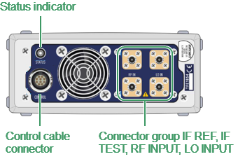
Rear panel of FET1854
The connection of the FET1854 module to the Analyzer is shown in the figure below.
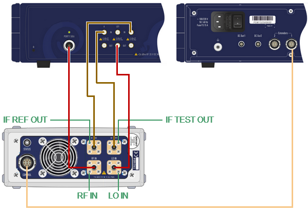
Connection diagram of the FET1854 module to the Analyzer
Measurement system components |
Connection |
|
|---|---|---|
Module |
Analyzer |
|
C4209 Vector Network Analyzer PC with S2VNA Software 1 or 2 Frequency Extension Modules 1 or 2 RF cables (N, male – SMA, male) 1 or 2 LO cables (SMA, male – SMA, male) 2 or 4 IF cables (SMA, male – SMA, male) 1 or 2 control cables Power supply and USB cables for Analyzer Set of calibration standards, test cables, and adapters |
RF IN |
PORT 1 PORT 2 |
LO IN |
LO 1 OUT LO 2 OUT |
|
IF REF |
R1 IN R2 IN |
|
IF TEST |
A IN B IN |
|