note |
Direct Receiver Access is available for C2209 and C2220 models. |
The Cobalt C2209 and C2220 Analyzers have adjustable port configurations with direct access to receivers. This option allows for a variety of test applications that require a wider dynamic and power range. Direct receivers access enables testing of high-power devices. Additional amplifiers, attenuators, various filters and matching pads for each port can be introduced into the path of the reference oscillator and the receiver path to provide optimal, near-realistic operation of the receivers and the DUT. In common mode, when direct access to the receivers is not used, additional ports are connected by jumper cable assemblies (See Cobalt Series).
Analyzers with direct access to the receivers have different functional schemes depending on the range of operating frequencies. The C2209 Analyzer, with a frequency range up to 9 GHz, has the following functional diagram (See figure below).
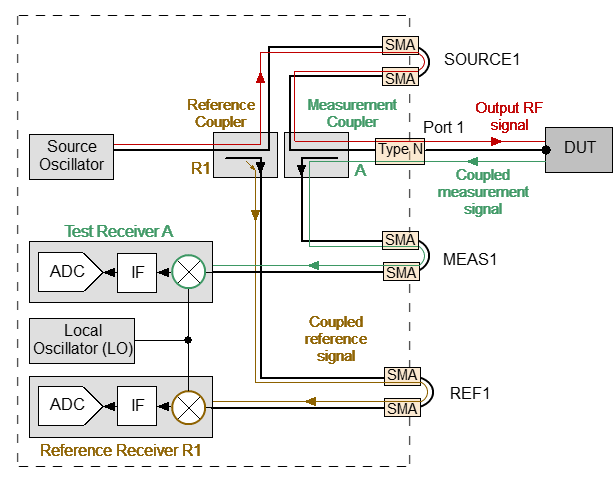
C2209 Analyzer signal propagation in common mode
In common mode, all additional port cable jumpers are connected. The Analyzer takes measurements using built-in modules (see above figure). If the jumpers are removed, external directional couplers, bridges, or amplifiers can be connected to the adjustable ports. The signal propagation corresponding to the direct access mode to the receivers is shown in the figure below.
For the C2209 Analyzer with a frequency range up to 9 GHz, there is no need to switch in S2VNA software to enable direct mode.
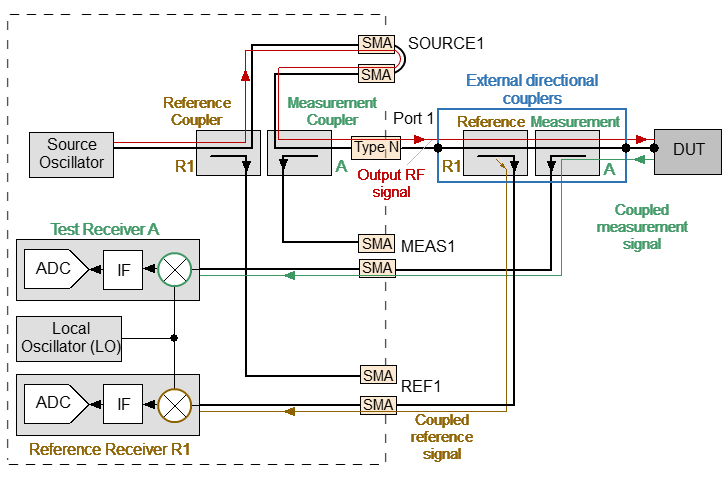
C2209 Analyzer signal propagation in direct receiver access mode
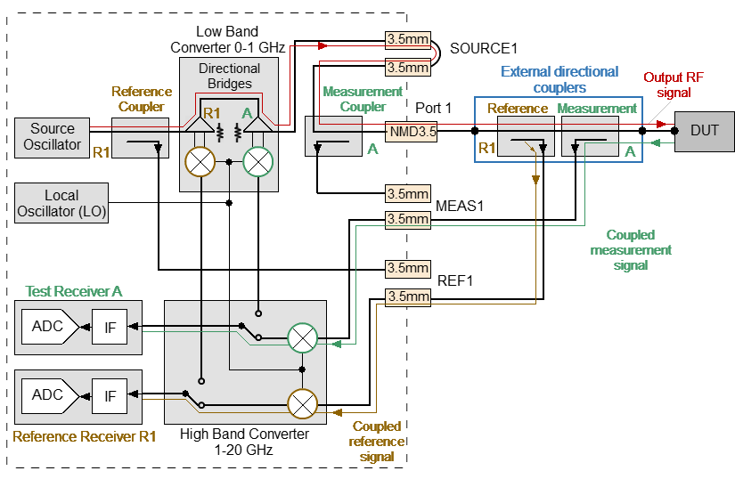
The C2220 Analyzer, with a frequency range of up to 20 GHz, has a more complicated functional diagram (See figure below). This Analyzer is a broadband instrument that uses two different internal devices for signal separation — the directional bridge and the directional coupler for each port, respectfully. Both devices operate together to provide the frequency coverage beginning from 100 kHz up to 20 GHz for reference and measurement paths separately.
The receiver path of the Analyzer includes low and high band converter units which work independently. The first of those operates in the frequency band below 1 GHz. For signal converting, it uses output signals transmitted from directional bridges (See figure below). The low band converter with bridges is merged into one physical module.
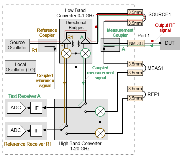
Signal propagation in common mode while the Analyzer operates in the frequency range between 100 kHz and 1 GHz
The other module — the high band converter, receives signals from directional couplers as shown in the figure below, and covers the rest of the operating frequency range.
In common mode, when all loops are connected, the Analyzer manages these converters and gathers reference and measurement signals in the entire frequency range for further analysis. This receiver design allows the user to achieve optimal raw (uncorrected) parameters such as directivity, source and load match, as well as providing higher dynamic range.
Signal propagation in common mode while the Analyzer operates in the frequency range between 1 GHz and 20 GHz
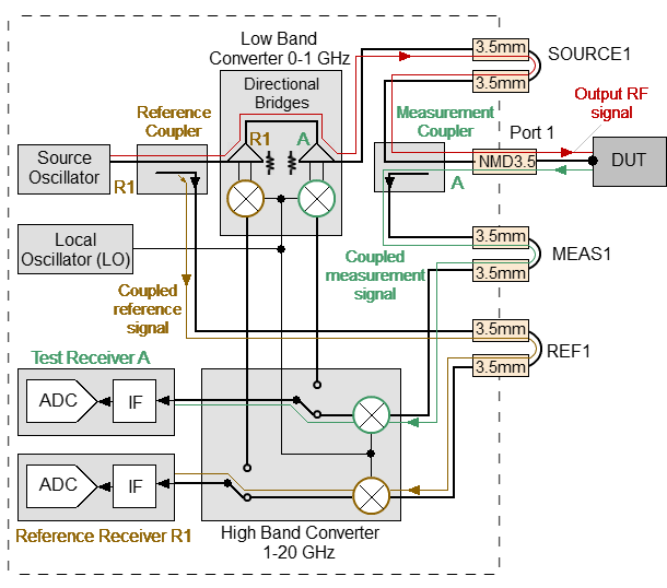
Typical configuration for direct receiver access mode is demonstrated below.
Typical signal propagation in direct receiver access mode
The Analyzer operates over the entire frequency range using only the high band converter.
It’s the most popular setup for applications requiring wider dynamic and power ranges. The above figure does not show external units, such as amplifiers, attenuators, directional devices (couplers or bridges) and so on, which are required for regular measurements. It is possible to use custom external directional devices for signal separation, which have specified parameters and work in the appropriate frequency range.
The C2220 has a special type of high band converter. It's able to process and convert input signals in the entire frequency range. In order to stop switching between low and high converters during signal sweep or receiver treatment, the analyzer offers an extra mode. This mode has a similar name, "Direct access to receivers" in the Analyzer software. It enables the user to manage the measurement switching process by pressing one single softkey.
It is recommended to apply this mode when performing measurements with any external directional devices. It will be particularly valuable when an external amplifier is used together with VNA internal directional devices. Any amplifier will block direct access to the internal bridge from the DUT side (refer to the figure below). It will decrease both the system effectiveness and measurement accuracy. In this case, the VNA can analyze signals derived from internal directional coupler only using the above-mentioned mode.
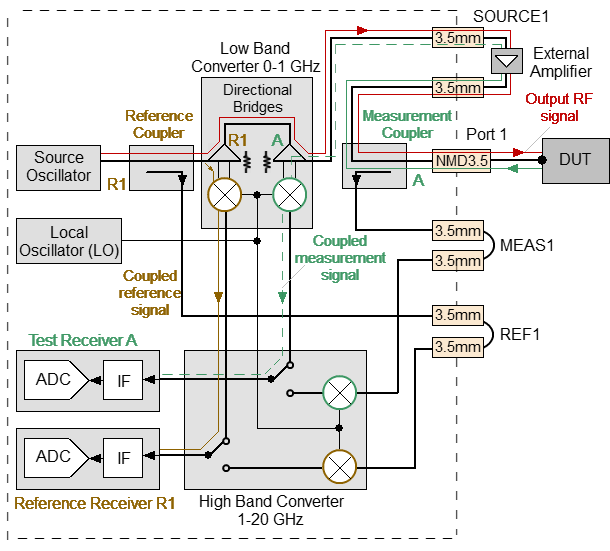
Signal propagation with external amplifier installed on oscillator path while the Analyzer operates in the frequency range between 100 kHz and 1 GHz
|
To enable/disable direct receiver access (for C2220 model only), use the following softkeys: System > Misc Setup > Direct Access To Receivers [ON | OFF] Note: The mode allows to carry out measurements with signals transmitted from external directional devices within the entire frequency range, eliminating the need for switching between low and high frequency ranges of the Analyzer. |


|
|