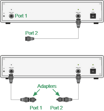
The test ports of the Analyzer are defined by means of calibration. The test port is a connector accepting a calibration standard in the process of calibration.
A type-N, 3.5 mm NMD, 2.4 mm NMD or 1.85 mm NMD connector on the front panel of the Analyzer will be the test port if calibration standards are connected directly to it.
Sometimes it is necessary to connect coaxial cables and/or adapters to the connector(s) on the front panel to interface with a DUT of a different connector type. In such cases, calibration standards are connected to the connector of the cable or adapter.
The figure below represents two cases of test port definition for 2-port measurements. The use of cables and/or adapters does not affect the measurement results if they are integrated into the process of calibration.

Test port defining
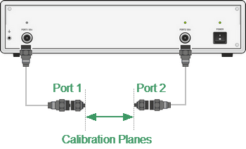
The term calibration plane is used in some cases. The calibration plane is an imaginary plane located at the ends of the connectors, which accept calibration standards during calibration.

Calibration planes