The Analyzer consists of the Analyzer Unit, some supplementary accessories, and a personal computer (which is not supplied with the package). The Analyzer Unit is powered and controlled by PC via USB-interface. The block diagram of the Analyzer is presented in figure below.
The Analyzer Unit consists of a source oscillator, a local oscillator, a source power attenuator, a directional coupler and other components which ensure the Analyzer operation. The test port is the source of the test signal. The incident and reflected signals from the directional coupler are supplied into the mixers, where they are converted into IF, and are transferred further to the 2-channel receiver. The 2-channel receiver, after filtration, digitally encodes the signals and supplies them for further processing (filtration, phase difference measurement, magnitude measurement) into the signal processor. The filters for the IF are digital and have passband from 10 Hz to 30 (100) kHz. The combination of the assemblies of directional couplers, mixers, and 2-channel receiver forms two similar signal receivers.
An external PC controls the operation of the components of the Analyzer. To fulfill the S-parameter measurement, the Analyzer supplies the source signal of the assigned frequency from the test port to the DUT, then measures magnitude and phase of the signal reflected by the DUT, and after that compares these results to the magnitude and phase of the source signal.
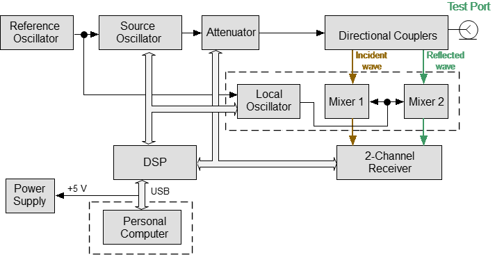
The 1-port VNA block diagram
RNVNA combines up to 16 1-port Analyzers through USB hub with ability to perform S21 and S12 scalar measurements. The hub is connected to the external computer. RNVNA software controls multiple 1-port Analyzers, creating multi-port vector network analyzer.
Optionally, TD-16 trigger signal distributors and FD-16 reference frequency distributors can be used. Using the TD-16 trigger signal distributor make it possible to connect all the analyzers with the common trigger signal bus that allows increase in measurement speed. Using the FD-16 reference frequency signal distributor makes it possible to connect all the analyzers with the common reference frequency signal, allowing increase in measurement accuracy and speed.
At a time, the signal source can be only one analyzer (active). Other analyzers (passive) will work as signal receivers. The analyzer is set to be active depending on the S-parameters measured in the display channel. For example, when measuring parameters S11 and |S21| the first analyzer will be active, when measuring |S12| and S22 — the second one. If the list of S-parameters is indicated in the display channel, several measurements will be made, where analyzers will change their roles.
The block diagram of the RNVNA is presented in figure below.
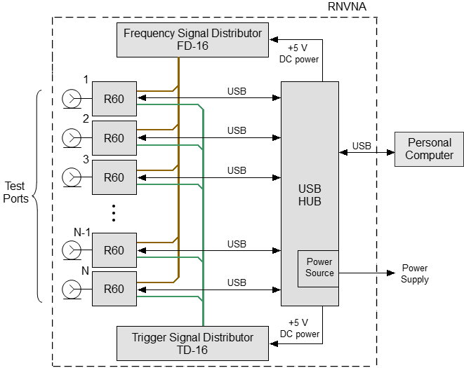
N is number of Analyzers.
RNVNA block diagram