A marker is a tool for numerical readout of a stimulus value and value of the measured parameter in a specific point on the trace. Up to 16 markers can be activated on each trace. A trace with two markers is shown in the figure below.
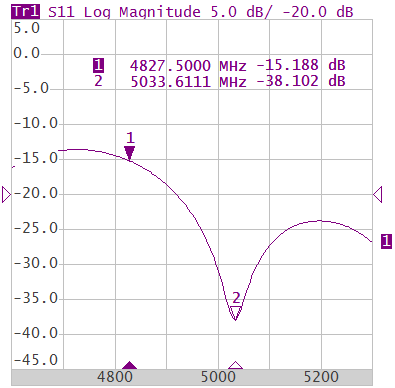
Trace with two markers
The markers allow to perform the following tasks:
•Reading absolute values of a stimulus and a measured parameter in selected points on the trace.
•Reading relative values of a stimulus and a measured parameter related to the reference point.
•Search for specific points on the trace (minimum, maximum, target level, etc.).
•Determining trace parameters (statistics, bandwidth, etc.).
•Editing stimulus parameters using markers.
Markers can have the following indicators:
1 ∇ |
Symbol and number of the active marker on a trace. |
Δ 2 |
Symbol and number of the inactive marker on a trace. |
|
Symbol of the active marker on a stimulus axis. |
Δ |
Symbol of the inactive marker on a stimulus axis. |

The marker data field contains the marker number, stimulus value, and the measured parameter value. The number of the active marker is highlighted in an inverse color.
The marker data field contents vary depending on the display format (rectangular or circular):
•In rectangular format, the marker shows the measurement parameter value plotted along Y-axis in the active format (See the table below).
Format Type Description |
Label |
Data Type (Y-axis) |
Measurement Unit (Y-axis) |
|---|---|---|---|
Logarithmic Magnitude |
Log Magnitude |
S-parameter logarithmic magnitude: , |
Decibel (dB) |
Voltage Standing Wave Ratio |
SWR |
|
Dimensionless value |
Phase |
Phase |
S-parameter phase from –180° to +180°:
|
Degree (°) |
Expanded Phase |
Expand Phase |
S-parameter phase, measurement range expanded to from below –180° to over +180° |
Degree (°) |
Group Delay |
Group Delay |
Signal propagation delay within the DUT: ,, |
Second (sec.) |
Linear Magnitude |
Lin Magnitude |
S-parameter linear magnitude: |
Dimensionless value |
Real Part |
Real |
S-parameter real part: |
Dimensionless value |
Imaginary Part |
Imag |
S-parameter imaginary part: |
Dimensionless value |
Cable Loss |
Cable Loss |
|
Decibel (dB) |
•In circular format, the marker shows three or four values listed in the table below.
Label |
Marker Readings (Measurement Unit) |
|||
|---|---|---|---|---|
Reading 1 |
Reading 2 |
Reading 3 |
Reading 4 |
|
Smith (Lin) |
Frequency |
Linear magnitude |
Phase (°) |
— |
Smith (Log) |
Frequency |
Logarithmic magnitude (dB) |
Phase (°) |
— |
Smith (Re/Im) |
Frequency |
Real part |
Imaginary part |
— |
Smith (R + jX) |
Frequency |
Resistance (Ω) |
Reactance (Ω) |
Equivalent capacitance or inductance (F/H) |
Smith (G + jB) |
Frequency |
Conductance (S) |
Susceptance (S) |
Equivalent capacitance or inductance (F/H) |
Polar (Lin) |
Frequency |
Linear magnitude |
Phase (°) |
— |
Polar (Log) |
Frequency |
Logarithmic magnitude (dB) |
Phase (°) |
— |
Polar (Re/Im) |
Frequency |
Real part |
Imaginary part |
— |
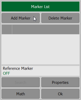
Marker Addition
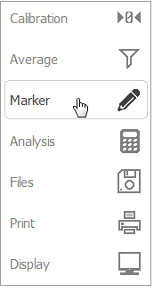
To enable a new marker, use the softkeys Markers > Add Marker on left menu bar.
|
note |
The new marker appears as the active marker in the middle of the stimulus axis. |
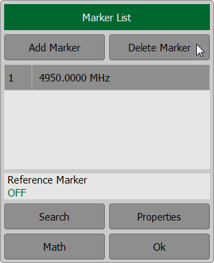
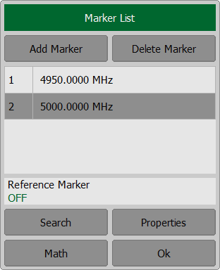
Marker Deletion
To delete a marker, use the softkeys Markers > Delete Marker.
|
note |
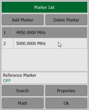
The active marker is highlighted in the Marker List dialog. |
Marker Activation
To activate a marker, use the softkey Marker. In the Marker List dialog click on the marker number to activate it.
|
note |
A marker can be activated by clicking on it. |
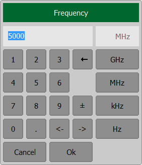
Marker Stimulus Value Setting
The active marker must be selected before setting the marker stimulus value. The stimulus value must be set by entering the numerical value from the keyboard, by arrows, by dragging the marker using the mouse (See Marker Stimulus Value Setting), or by enabling the search function (See Marker Position Search Functions).
To set the marker stimulus value, use the softkey Marker. Select a required marker from the Marker List dialog. Double click on the marker stimulus value in the table and enter the stimulus value using the on-screen keypad. Complete the setting by clicking Ok.
|
note |
To enter the stimulus numerical value in the marker data field, click on it. |