Procedure for installing (removing) the protective housing:
1. Unscrew using a PH1(PZ1) screwdriver:
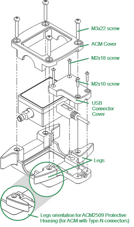
•4 pcs. M3×22 screws on the ACM cover. Remove the ACM cover (See figure below).
•2 pcs. M2×18 screws and 2pcs. M2×10 screws on the USB connector cover. Remove the cover.
2. Install (remove) the ACM with the USB cable plugged in. The USB cable must be disconnected from the computer. The orientation of the instrument and the legs of the housing must comply with the figure below.
note |
For the ACM2509, turn the legs over for convenient wrench access to the Type-N connectors. |
3. Install the USB connector cover, then the ACM cover, using the same screws.
note |
The head of the screw should be slightly recessed. Tighten without using force, making sure not to allow the material to bulge on opposite side. |
Example of housing installation (for ACM2509-011)