In this section the front panel of Analyzer are shown further, along with the controls located on panel.
PXIe-S5090 front panel is represented in the following figure.
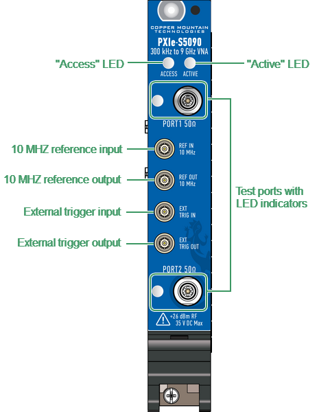
PXIe-S5090 front panel
The parts of the front panel
Test ports with LED indicators |
The PORT 1 and test PORT 2 are intended for DUT connection. PXIe-S5090 has 3.5 mm female test ports. Each test port has a LED indicator. The test port can be used either as a source of the stimulus signal or as a receiver of the response signal from the DUT. The stimulus signal can only appear on one port at a time. When connecting the DUT to only one test port of the Analyzer, it is possible to measure the reflection parameters (e.g. S11 or S22) of the DUT. When connecting the DUT to all test ports of the Analyzer, it is possible to measure the full S-parameter matrix of the DUT. |
"Access" status LED |
Indicates the basic hardware status of the CMT PXIe - S5090 module. The LED indicates the following statuses: •OFF — Power is OFF. •AMBER — Power is ON but the firmware is not running. •GREEN — The firmware is running and the hardware has been initialized. The module is ready to be programmed by IVI driver. •RED — The module has detected a hardware error, such as a factory calibration EEPROM checksum error, frequency alignment error, RF power trip at overload. |
"Active" status LED |
The LED identifies the state of the CMT PXIe - S5090 module. The LED indicates the following states: •OFF — The module is not yet functional. •AMBER — The module is armed and waiting for a trigger. •GREEN — The module has received a Start Trigger. This state also indicates that the module is making a measurement. •RED — The module has detected that the PLL is unlocked, especially when using the external reference source. |
External trigger signal input connector |
This connector allows to connect an external trigger source. Connector type is SMB male. TTL compatible inputs of 0 V to 5 V magnitude with minimum 2 μsec pulse width. Input impedance is at least 2 kΩ. |
External trigger signal output connector |
The external trigger signal output port can be used to provide trigger to an external device. The port outputs various waveforms depending on the setting of the Output Trigger Function: before frequency setup pulse, before sampling pulse, after sampling pulse, ready for external trigger, end of sweep pulse, measurement sweep. |
External reference frequency input connector |
External reference frequency is 10 MHz, input level is 0 dBm ± 3 dB, input impedance at «Ref In» is 50 Ω. Connector type is SMB male. |
Internal reference frequency output connector |
Output reference signal level is 1 dBm ± 2 dB at 50 Ω impedance. «Ref Out» connector type is SMB male. |
note |
The LED indicator identifies the test port which is operating as a signal source. |
WARNING |
Do not exceed the maximum allowed power of the input RF signal (or maximum DC voltage) indicated on the front panel. This may damage Analyzer. |