The Vector Network Analyzer (VNA) is a tool for accurate measurement of complex transmission and reflection coefficients (S-parameters) of a Device Under Test (DUT).
The Analyzer described in this manual consists of a PXI hardware module (Analyzer for RF measurements) and the supplied the S2VNA software. The module is installed in a PXI chassis and communicates with the S2VNA software installed on the PXI system controller via the internal PCIe bus. This application controls the RF measurement module, receives and processes the received raw data, and presents the calibrated results to the user in various graphical formats.
The block diagram of the Analyzer is represented in the following figure.
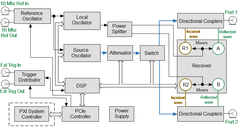
The block diagram of the Analyzer
The Analyzer consists of the following functional blocks: a Reference Oscillator, a Source Oscillator, a Local Oscillator, a power control Attenuator, a Switch, a Power Splitter, two Dual Directional Couplers, a four-channel Receiver, a digital signal processor (DSP), and a Power Supply.
A tunable Source Oscillator is the test signal source. This Source Oscillator design is based on digital frequency synthesizers. An internal Reference Oscillator provides the source oscillator with a stable reference signal.
The Local Oscillator (LO) generates signals using digital frequency synthesizers at an offset from the Source Oscillator which is equal to the Intermediate Frequency (IF) which will be digitized by the VNA IF circuit.
The Local Oscillator is the source of the LO signal for the receiver.
The Power Splitter distributes the LO signal between the four Receivers.
A programmable Attenuator controls the power level of the test signal. This Attenuator is an executive unit of the automatic power control system. For example, when a power calibration has been completed, the Power Correction function uses this Attenuator. Also, the Analyzer can sweep over the output power range at a fixed frequency of test signal using this Attenuator. The Attenuator is controlled by setting the signal power level at the output of the measurement port. The range of signal power levels is specified at the output for power sweep mode.
Switch changes the direction of the test signal through the DUT, switching the Source Oscillator signal between the two Directional Couplers. Thus, any port can be the source or receiver of a signal. If Port 1 is the source, Port 2 will be the receiver and vice versa. All the S-parameters can be measured by making only one DUT connection.
Directional Couplers separate the incident wave and reflected waves of signal transmitted through a DUT.
The incident and reflected signals from the two Directional Couplers are applied to a multi-channel Receiver. The multi-channel Receiver of the two-port Analyzer consists of four identical channels (two channels per port). The reference receiver processes the incident wave, a measuring receiver processes the reflected wave. The Reference receiver is indicated as R with the index corresponding to the port number. The measuring receiver is indicated as A or B. Receiver Mixers convert the signal to an IF frequency. Analog-to-digital converters in a multi-channel receiver convert these IF signals to a sequence of digital samples and supply them to DSP. The DSP performs primary signal processing (filtering, phase difference estimation, magnitude measurement). The user selected IF Bandwidth is applied by the DSP filter.
After the primary signal processing, the DSP transmits the information to the control S2VNA software running on an PXI system controller. Communication is provided by a PCIe controller. This software applies calibration and performs the final calculations and displays the measurement results on the screen of PC. The software also controls the operation of the hardware of the Analyzer.