The front and rear panel view of the Analyzers is represented in the figures below.
|
|
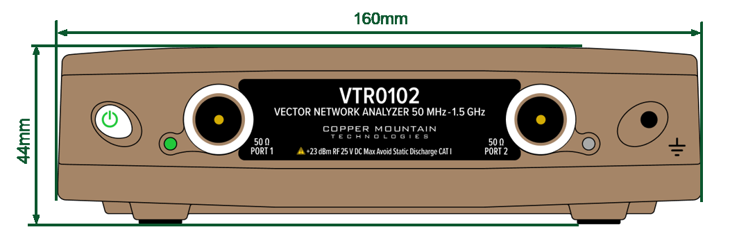
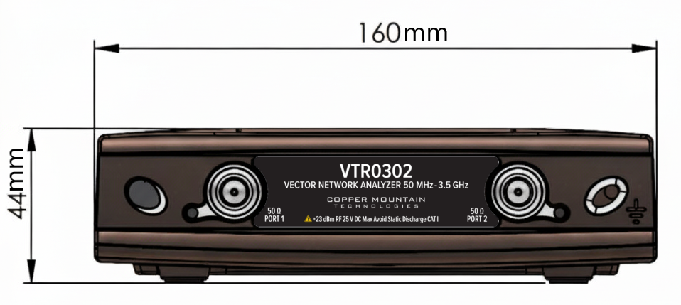
VTR0102 and VTR0302 Front Panel
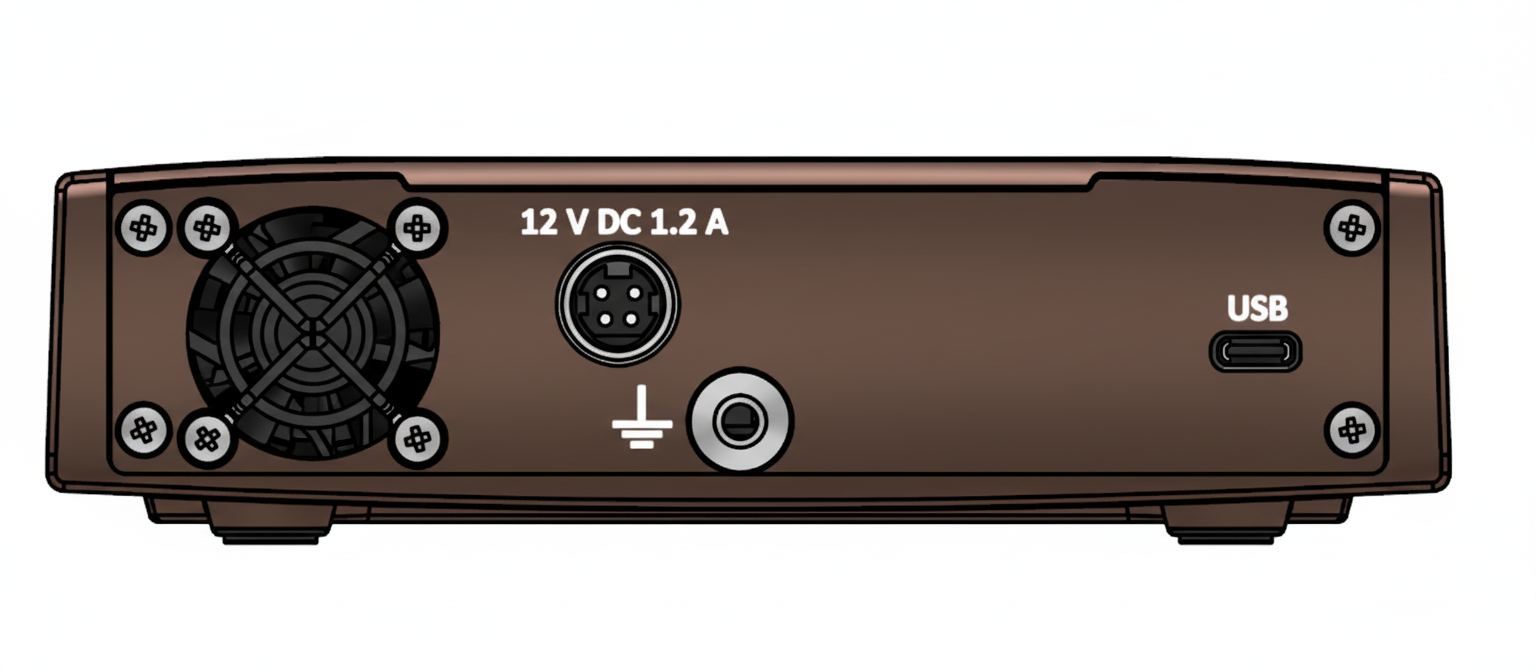
VTR0102 and VTR0302 Rear Panel
Parts of the VTR0102 and VTR0302
Power Button
Switches the Analyzer ON and OFF.
The Analyzer can be turned ON/OFF at any time. The VNA loads its operating firmware from the PC each time upon powering up. The process will take approximately 10 seconds, after which the Analyzer will be ready for operation.
Test ports
The type-N 50 Ω test port 1 and test port 2 are intended for DUT connection. Test port 1 is used as a source of the stimulus signal and receiver of the incident and reflected wave signals. Test port 2 is used as a receiver of the response signal of the DUT.
If the DUT is connected to test port 1 of the Analyzer, it is possible to measure the reflection parameter S11 of the DUT. If the DUT is connected to both test ports of the Analyzer, it is possible to measure S11 and S21 of the DUT.
Each test port has an LED indicator. A test port can be used either as a source of the stimulus signal or as a receiver of the response signal from the DUT. The stimulus signal can only appear on the only one port at a time.
USB Connector
The type C USB 2.0 port is intended for connection to USB port of the personal computer via the supplied USB cable.
Ground Terminal
To avoid electric shock, use this terminal for grounding.
The Ground terminal allows to connect the body of the Analyzer directly to the test station ground in order to ensure electrical safety. Located on both the front and the back panels.
Power Cable Receptacle
The power supply receptacle is intended for an external DC power supply voltage of 12V.