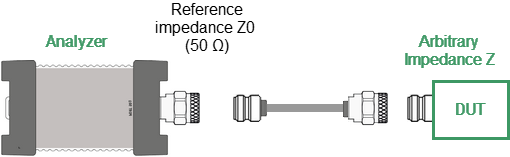
The default reference impedance of a port is equal to the impedance of the connectors (50 or 75 Ω). But in the process, it is often required to measure DUT with arbitrary resistance (See example in the figure below), not equal to the impedance of a port. In this case, it is possible to convert the reference impedance to an arbitrary impedance value using the software.
Example of measuring a DUT with an arbitrary impedance by the Analyzer with reference impedance 50 Ω
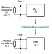
Port reference impedance conversion is a function that mathematically converts the matrix of S-parameters measured at the reference impedance of port Z0 to the matrix of S-parameters measured at an arbitrary impedance of port Z1 (See figure below). The function is also referred to as the renormalization transformation of S-parameters.
Port reference impedance conversion
Renormalization can be based on two alternative microwave circuit theories, whose conversion formulas may yield different results if the reference impedance of at least one test port has a non-zero imaginary part. The first theory is "A General Waveguide Circuit Theory" (R.B.Marks and D.F.Williams). The second theory is the "Power waves and the Power Scattering Matrix" (K.Kurokawa).
note |
The source value of the Z0 port reference impedance (commonly 50 Ω) is defined in the process of the calibration. It is determined by the characteristic impedance of the calibration kit and its value. |

Fixture Simulation Menus
|
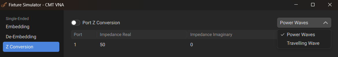
To enable/disable the port reference impedance conversion function: Fixture > Z0 Conversion [ON|OFF] Or go into the Fixture Wizard and go to the Z Conversion tab. |
|
To enter the value of the simulated impedance of Port n: Fixture > Fixture Wizard > Z Conversion > Impedance Real Fixture > Fixture Wizard > Z Conversion > Impedance Imaginary |
|
To choose the theory according to which the renormalization of S-parameters is performed: Fixture > Fixture Wizard > Z Conversion Use the dropdown menu in the top right to select either Power Waves or Travelling Waves. |
|
|