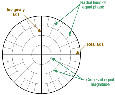
The Polar format is used to display the amplitude and phase of the reflection coefficient () when measuring S11 . The complex reflection coefficient values are displayed on the polar diagram in the complex plane. The complex plane is formed by the real horizontal and the imaginary vertical axes. The grid lines correspond to points of equal amplitude and phase (See figure below).
Polar format
note |
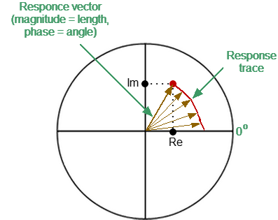
On circular diagrams (Polar and Smith chart), any point of the trace can be defined in the following two ways (See figure below): •Coordinates of the point (Re, Im) on the real and imaginary coordinate axes. •Parameters of the vector directed to the point from the center of the diagram. The length of this vector is equal to the response amplitude, and the angle between the vector and the positive part of the real coordinate axis is equal to the phase of the response. The angle is calculated counterclockwise.
|
note |
Traces on all types of Smith chart and polar format are the same, the Analyzer replaces the base grid and default marker format when switching formats. |
The Polar format diagram with the characteristic points is shown in the figure below.
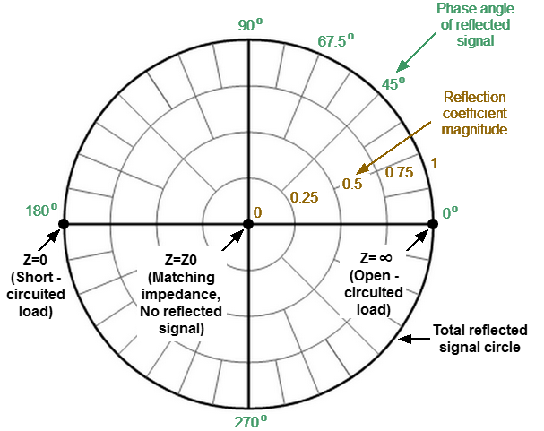
Properties of Polar format
Basic properties of the Polar format:
•The center of the diagram corresponds to the reflection coefficient = 0 (reference impedance Z0 on the input test port of the DUT when measuring S11