This is a series of full-size rack-mounted VNAs that delivers lab grade performance, with the maximum standard software feature set (except Planar 304/1). This series includes an Analyzer with direct access to receivers.
The front view of the Analyzers is represented in the figures below.
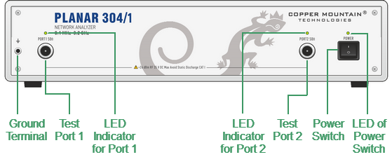
Planar 304/1 front panel
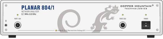
Planar 804/1 front panel
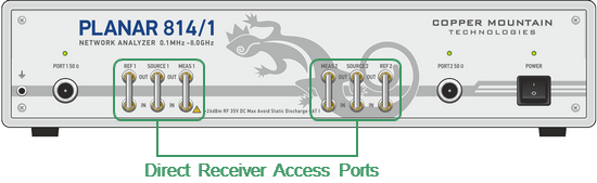
Planar 814/1 front panel
Part of front panel
Power Switch
|
Switches the Analyzer ON and OFF. The switch interrupts the power line of the instrument in this model. The Analyzer can be turned on/off at any time. The VNA loads its operating firmware from the PC each time upon powering up. The process will take approximately 10 seconds, after which the analyzer will be ready for operation. |

note |
The USB driver will be installed onto the PC when the analyzer is turned on for the first time. The driver installation procedure is described in Software Installation. Some PCs may require re-installation of the driver in case of change of the USB port. |
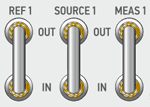
Test Ports

note |
The LED indicator identifies the test port which is operating as a signal source. |
Caution |
Do not exceed the maximum allowed power of the input RF signal (or maximum DC voltage) indicated on the front panel. This may lead to damage of the Analyzer. |
Ground Terminal
|
Use the terminal for grounding. To avoid damage from electric discharge, connect the ground terminal on the body of the Analyzer to a reliable earth ground shared with the DUT in the test environment. |

Adjustable Ports Configurations (Planar 814/1 model only)
|
Adjustable port configurations with direct access to the receivers of the VNA provide for a variety of test applications requiring wider dynamic and power range. Direct receiver access enables testing of high power devices. Additional amplifiers, attenuators, various filters and matching pads for each of the ports may be introduced in reference oscillator and receiver path to ensure optimal operation of the receivers. |